



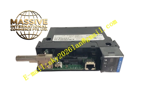
Description
Honeywell TC-CCR013
Technical Specifications
- Compatible bus: ControlNet fieldbus
- Redundancy configuration: Dual BNC coaxial interfaces for A/B networks
- Communication rate: 5 Mbps
- Maximum bus node count: 99
- Bus transmission distance: 100 meters coaxial cable
- Backplane interface: TDC3000 V-series rack bus
- Supply power: 5 V DC from backplane
- Operating temperature: 0 °C to +60 °C
Functional Features Dual redundant network communication, automatic seamless switchover to backup network when one bus disconnects. On-board 75 Ω termination resistors, eliminates high-speed bus signal reflection. Bus node status diagnosis, automatically identifies node dropouts and communication conflicts. On-board LEDs indicate A network and B network communication activity and fault status. Per-frame CRC verification for all communication data, transmission error rate below 10^-9. Supports integration of remote I/O, smart valve positioners and VFDs.
Application Scenarios Communication connection between TDC3000 controllers and remote I/O stations Fieldbus integration for VFDs and smart devices Spare part replacement for legacy ControlNet interface card communication faults Fieldbus expansion retrofits for production line control systems
Performance Parameters
- Dual network switchover time: ≤1 ms
- Communication latency: ≤100 μs
- Fault detection response: ≤100 ms
- Mean time between failures: 600,000 hours
- ESD protection: ±8 kV contact discharge
Material Composition FR4 high-speed PCB substrate ControlNet bus controller chip High-speed differential transceiver Gold-plated BNC coaxial connectors Optocoupler isolation devices Metal shielded front panel
Structural Features Standard Eurocard dimensions, inserts into the dedicated communication slot of the V-series rack. Front panel has two BNC interfaces for A and B redundant networks. LED array displays dual network communication status. Metal shielded enclosure contains high-speed bus electromagnetic radiation. Impedance-controlled 75 Ω trace layout matches coaxial cable characteristic impedance.
Working Principle The card acts as the master node on the ControlNet bus, polling all connected field devices in a fixed schedule. Process data uploaded by field devices travels over the dual redundant bus back to the card, packaged for transmission to the controller for logic operation. Control commands issued by the controller are sent to corresponding field devices over the dual network. Bus monitoring circuit continuously checks signal quality on both links; when the active link is abnormal, automatic switchover to the backup link occurs, maintaining uninterrupted communication.
Installation Requirements Connect A and B redundant bus coaxial cables to corresponding BNC interfaces. Install 75 Ω termination resistors at the bus far end. Scan all nodes on the bus after power-up, confirm all nodes are online in diagnostic software. Single-point shield grounding for coaxial cable shields.
Usage Notes Missing termination resistors at the bus end causes signal reflection and high packet loss. Loose BNC connectors cause bus communication dropout; tighten connectors during routine maintenance. Disconnect bus power when adding new field devices, to avoid disrupting active bus communication. Card station address must not conflict with other devices on the bus; address collision causes entire bus failure.







