



Description
Honeywell TK-PDD011
Technical Specifications
- Monitored objects: All I/O cards, power modules and fan units in the cabinet
- Diagnostic precision: Channel-level fault location
- Communication interface: Connects to TPS LCN high-speed communication bus
- Supply power: 5 V DC from backplane
- Fault event record capacity: 512 time-stamped events
- Operating temperature: 0 °C to +60 °C
- Front panel LEDs: 3 status lights for power normal, system fault, communication normal
Functional Features Real-time scan of all card health status, identifies channel faults, card communication failure, power abnormality and fan stop events. Fault information includes precise location and timestamp, uploaded to operator station for display. Supports remote diagnostic reading; maintenance staff can view full cabinet status from the operator station. Fault level classification, distinguishes general alarms from critical faults. On-board storage records historical fault events, for post-event traceability analysis. Diagnostic scan cycle: 100 ms full cabinet inspection.
Application Scenarios Centralized monitoring of cabinet device status for TPS systems Maintenance retrofits for long fault troubleshooting time in legacy systems Equipment health management for critical device control systems Diagnostic function assembly for new TPS cabinets
Performance Parameters
- Fault location precision: Exact to specific board and specific channel
- Fault upload latency: ≤500 ms
- Event record retention: 10 years without power
- Diagnostic scan cycle: 100 ms
- False alarm rate: ≤0.1%
Material Composition FR4 PCB substrate FPGA diagnostic processing chip Non-volatile memory chip Optocoupler isolation devices Gold-plated board-to-board connector Flame retardant plastic front panel
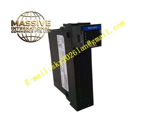
Structural Features Small rectangular daughter board, installed in the dedicated slot adjacent to the main controller. Rear gold fingers mate to the backplane diagnostic bus. Front panel LED array displays system health status. Diagnostic bus traces are physically separated from power traces.
Working Principle After power-up, the daughter board polls status registers of all cards and power supplies in the cabinet in fixed order via the backplane diagnostic bus. When detecting card channel faults, power output abnormality or fan stop events, the board generates corresponding fault codes, marking fault location and event timestamp. Fault events are first written to on-board storage chip, then transmitted over the LCN bus to the operator station for display. Historical fault records are permanently stored, available for maintenance staff to retrieve at any time.
Installation Requirements Insert the daughter board into the dedicated slot only when power is off, press until gold fingers are fully seated. Read the diagnostic list on the operator station after power-up, confirm all device status is correctly recognized. Configure fault alarm level rules, route critical faults to audible and visual alarms. Trigger a single channel fault during commissioning, verify diagnostic location accuracy.
Usage Notes Diagnostic board offline does not affect normal control system operation; it only removes centralized monitoring functionality. When the storage chip fills with old records, export and back up data regularly to avoid overflow overwriting the earliest events. Loose diagnostic bus connector causes partial device status loss; inspect connector lock status regularly. Fault code interpretation requires reference to TPS system manual; never judge fault location based on experience alone.







