



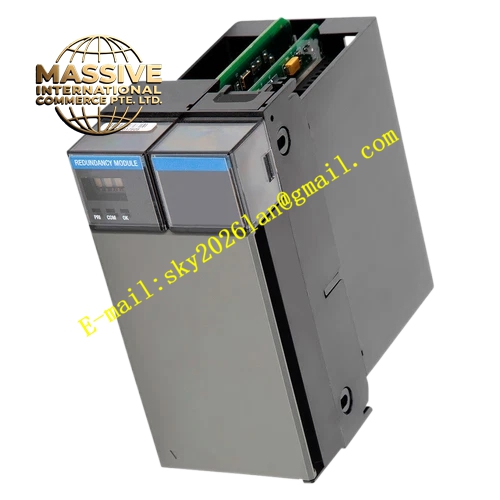
Description
Honeywell TK-PRR021 51309288-375
Technical Specifications
- Backplane Interface: C200 dedicated redundancy bus
- Power Supply: 5VDC and 3.3VDC from rack backplane
- Operating Ambient Temperature: 0°C to +60°C
- Storage Temperature: -40°C to +85°C
- Relative Humidity: 5% to 90% RH non-condensing
- Redundancy Sync Speed: High-speed parallel data bus
- Mounting Method: Plug-in slot installation on C200 rack
- Certification: UL, CE, TÜV, RoHS
Functional Features It supports 1:1 hot standby redundancy mode for paired C200 controllers. It synchronizes all control logic, setpoint values, alarm status and I/O data between primary and standby unit continuously. It monitors heartbeat signal, hardware fault and execution status of both controllers. It triggers automatic switchover to standby controller within milliseconds once primary controller encounters fault. It provides front panel LED indicators for power, redundancy active, sync status and module fault. It supports hot swap replacement while the control rack keeps online. It locks configuration data inside non-volatile memory and retains data after power loss. It rejects invalid configuration mismatch to prevent abnormal switchover.
Application Scenarios Petrochemical plant redundant C200 control cabinet Chemical reactor continuous process control system Power plant boiler and auxiliary control DCS rack Natural gas compression station safety control system Refinery furnace and distillation unit redundant control configuration
Performance Parameters
- Redundancy Switchover Time: Less than 20ms
- Mean Time Between Failures: 850000 hours
- Insulation Resistance: Greater than 1000 MΩ
- ESD Immunity: 8kV contact discharge
- Synchronization Data Bandwidth: Supports full CEE control database mirroring
Material Composition FR4 flame retardant conformal coated multilayer PCB High-speed FPGA redundancy processing chip Flash and SDRAM memory chips TVS surge suppression components Gold plated edge connector for rack backplane Metal front panel with extraction handle and LED indicators UL94 V-0 plastic locking buckle
Structural Features Standard C200 rack plug-in module form factor. Front metal panel carries tri-color LED indicators and extraction handle. Rear gold plated edge connector mates with rack backplane power and redundancy bus. Internal PCB layout separates high-speed sync signal circuit and power circuit to reduce electromagnetic interference. Anti-key notch prevents reverse insertion into rack slot. Locking clip secures module firmly after installation. Internal shielding structure reduces signal crosstalk during data synchronization.
Working Principle After power on, paired TK-PRR021 modules establish bidirectional synchronization channel. The primary controller executes control logic and sends real-time runtime data to standby controller through redundancy bus. Standby controller keeps all data synchronized and runs control algorithm in tracking mode without outputting control command. When heartbeat loss, hardware failure or watchdog fault is detected on primary controller, redundancy module immediately transfers control ownership to standby controller. Standby controller takes over all I/O communication and control output without disturbance to process variables. Diagnostic circuit uploads fault and switchover event to Experion PKS operator station.
Installation Requirements Wear anti-static wrist strap before handling and installation. Insert two TK-PRR021 modules into designated paired slots of C200 redundant rack. Align anti-misalignment notch and lock front handle. Complete redundant controller configuration in Experion engineering workstation. Power on rack and wait for module self-test and synchronization completion. Verify redundancy active status and LED indication. Test manual switchover function from engineering station to confirm bumpless transfer.
Usage Notes Two matching TK-PRR021 modules must be used together for redundancy configuration. Do not scratch gold plated edge connector surface during handling. Do not remove one module while the other is running without isolating rack power. Keep cabinet internal temperature stable within specified range. Do not modify PCB trace or replace non-specified internal components.







