



Description
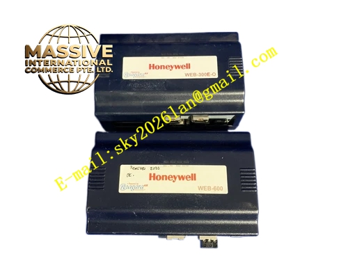
Honeywell WEB-300E
Technical Specifications
- Processor: PowerPC 405, 400MHz
- Operating System: QNX real-time operating system
- Software Platform: Niagara AX
- Onboard Ports: Dual Ethernet ports, RS232, RS485 serial ports
- Power Supply: 24VAC / 24VDC
- Operating Ambient Temperature: 0°C to +60°C
- Storage Temperature: -40°C to +85°C
- Relative Humidity: 5% to 90% RH non-condensing
- Mounting Method: DIN rail or wall mounting
- Certification: UL, CE, FCC, RoHS
Functional Features It executes standalone control logic for HVAC, VAV and lighting control. It supports BACnet IP, BACnet MS/TP, Modbus RTU, LonWorks and other open protocols. It provides built-in web server, users access real-time graphics, trend and alarm page via browser without dedicated client software. It supports automatic data trending and historical log storage. It generates alarm message and sends notification via email. It supports time schedule, holiday schedule and energy management strategy. It supports two optional communication expansion boards and optional 16-point or 34-point I/O modules. It provides SRAM data backup to avoid configuration loss during power interruption. Optional backup battery extends runtime for data recording. It supports remote configuration, firmware upgrade and system diagnosis from engineering workstation.
Application Scenarios Small and medium building HVAC automation control Remote site energy monitoring and metering gateway Retail store lighting and air conditioning integrated control Commercial building VAV box centralized supervision Plant auxiliary building BMS integration and data collection
Performance Parameters
- Maximum Device Integration Capacity: Increased 20% compared with WEB-200
- Mean Time Between Failures: 720000 hours
- Ethernet Communication Speed: 10/100Mbps auto negotiation
- Serial Port Baud Rate: Configurable from 1200bps to 115200bps
- Data Log Retention: Depends on internal flash and optional extended storage
Material Composition Metal alloy housing with powder coating PowerPC processor module Flash memory and SRAM memory chips Ethernet PHY and serial communication transceiver chips Status LED indicator array DIN rail mounting bracket Internal switching power circuit UL94 V-0 plastic terminal block
Structural Features Compact rectangular housing designed for cabinet DIN rail installation. Front panel carries status LED indicators and Ethernet, serial communication ports. Terminal block for power supply and field bus wiring is arranged on bottom side. Internal circuit board is separated into power zone and communication control zone to reduce interference. Metal housing provides electromagnetic shielding. Expansion slot on internal circuit supports optional communication daughter board installation. Anti-slip DIN rail clip prevents loose mounting under vibration.
Working Principle After power on, QNX real-time system loads Niagara AX station firmware. It communicates with field devices via Ethernet and serial ports, reads sensor value and device status. It runs control logic, schedule and energy strategy according to configured program. It generates control output commands to field actuators and I/O modules. It stores trend data and alarm event into internal memory. Web server package real-time graphics and data into HTTP page and respond to browser access request. It converts different industrial protocol data to realize cross-protocol gateway function. When power failure occurs, SRAM retains runtime configuration and historical data.
Installation Requirements Mount controller on DIN rail inside BMS control cabinet. Connect 24VAC or 24VDC power supply to dedicated power terminal. Wire Ethernet cable to LAN1 primary port and LAN2 secondary port for network. Connect RS485 bus to field BACnet MS/TP or Modbus devices. Assign static IP address and configure Niagara station from engineering tool. Download control strategy, graphic page and protocol mapping. Verify web access function from PC browser. Separate field bus cable from high voltage AC power cable.
Usage Notes Do not apply voltage exceeding rated 24V range to power terminal. Keep controller away from high temperature, dust and corrosive gas environment. Complete station backup before firmware upgrade. Assign network firewall access rule for remote web access. Check serial bus terminal resistor setting for RS485 network.







