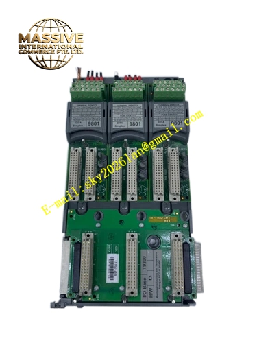
Description
ICS Triplex T3401
Technical Specifications
| Parameter | Specification |
|---|---|
| Manufacturer | ICS Triplex (Rockwell Automation) |
| Product Series | Regent System |
| Module Type | Simplex Digital Input Module |
| Input Channels | 16 independent discrete input channels |
| Nominal Input Voltage | 24 V DC |
| Input Voltage Range | 14 VDC to 30 VDC |
| Redundancy Architecture | Simplex (1oo1D) |
| Signal Isolation | Opto-galvanic isolation barriers |
| Chassis Compatibility | T3300 Regent 19-inch I/O Chassis (Slots 4–13) |
| Power Supply | +15 V DC from chassis backplane |
| Operating Temperature | 0°C to 60°C |
| Extended Temperature | -40°C to +70°C (some configurations) |
| Vibration Resistance | 5g RMS |
| Shock Resistance | 30g |
| Weight | 0.85 kg to 1.2 kg (by configuration) |
| Dimensions | 100 mm × 120 mm × 75 mm |
Functional Features
- 16 Independent Input Channels: High-density channel count optimizes I/O capacity per chassis slot
- Wide Input Voltage Range: Accepts 14 VDC to 30 VDC signals, accommodating various field device output levels
- Comprehensive Isolation: Opto-galvanic isolation barriers separate field loops from the internal processor backplane
- Simplex Architecture: Single-channel processing with diagnostic coverage suitable for standard automation applications
- Direct Chassis Integration: Mounts directly into standard I/O slots of the T3300 Regent chassis
- Efficient Power Operation: Low power dissipation drawing directly from the chassis +15 V DC bus
- High Environmental Tolerance: Operates reliably from -40°C to +70°C with resistance to 5g vibration and 30g shock
Application Scenarios
- PLC system digital input expansion
- Machine control system switch monitoring
- Process automation limit switch interfaces
- Control panel pushbutton and selector switch inputs
- Industrial gate and door system position monitoring
- Motor starter auxiliary contact feedback
- Safety interlock switch status detection
- General-purpose discrete signal acquisition
Performance Parameters
- Input Response Time: Fast state change detection for real-time control
- Signal Validation: Onboard logic validates input states before transfer to the controller
- Isolation Strength: High-voltage isolation withstands destructive field fault conditions
- Channel Density: 16 channels per module maximizes I/O density in control cabinets
- Power Efficiency: Minimal power draw from the chassis backplane
Material Composition
- Enclosure: Industrial-grade metal housing with corrosion-resistant finish
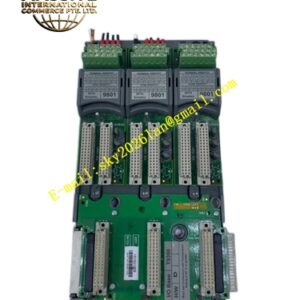
- Circuit Board: Multilayer PCB with optocoupler isolation circuits
- Optocouplers: High-speed industrial-grade optocouplers for channel isolation
- Input Protection: Overvoltage and transient protection components on each channel
- Connectors: High-reliability backplane and field terminal connectors
Structural Characteristics
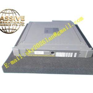
- Standard Regent I/O Form Factor: Designed for seamless integration into T3300 chassis
- Front-Panel Terminals: Screw terminals or spring-clamp connectors for field wiring
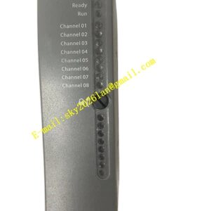
- Status LEDs: Individual channel status indicators and module health LED
- Backplane Interface: Direct plug-in connection to the T3300 chassis backplane
- Compact Design: Space-efficient packaging maximizes I/O density
Working Principle
Each of the 16 input channels receives a discrete 24 VDC signal from a field device such as a switch, proximity sensor, or relay contact. The input signal passes through an optocoupler that provides galvanic isolation between the field wiring and the internal logic circuits. The isolated signal is conditioned, filtered, and validated by onboard logic before being placed on the chassis backplane for reading by the Regent controller. The module continuously monitors all 16 channels and reports their states to the controller during each scan cycle.
Installation Requirements
- Install in Slots 4 through 13 of the T3300 Regent I/O chassis
- Use shielded cables for field wiring in electrically noisy environments
- Ensure proper grounding of cable shields
- Connect field devices that provide compatible 24 VDC output signals
- Verify chassis power supply capacity before adding modules
- Follow proper electrostatic discharge procedures during handling
Operating Precautions
- Verify input voltage levels remain within the 14–30 VDC range
- Monitor channel LEDs for abnormal indication
- Do not exceed the rated isolation voltage between field and logic circuits
- Maintain environmental conditions within specified temperature ranges
- Inspect terminal connections periodically for looseness or corrosion
- Replace failed modules with identical part numbers to ensure compatibility