Description
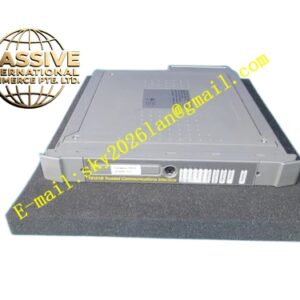
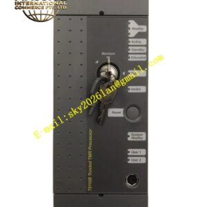
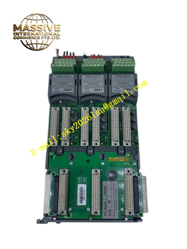
Ics Triplex T8850
Technical Specifications Total channel quantity 40, divided into five electrically‑isolated groups with 8 channels per group. Operating supply voltage 24VDC. Acceptable wire gauge range from 12AWG to 28AWG. SmartSlot connector for back‑plane connection. Screw‑clamp terminal blocks for field wiring. Operating temperature range 0‑60°C. Protection class IP20. DIN‑rail mounting compatible. Typical power consumption 300mA. Relay contact rating 3A at 24VDC
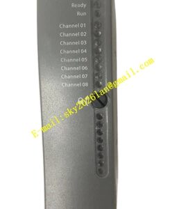
Functional Features Isolated channel group layout reduces cross‑channel fault propagation. On‑board LED indicators display field power supply status. Supports hot‑swap replacement of corresponding output modules without field cable modification. Standard two‑wire field device connection mode. Internal circuit provides transient‑voltage suppression for field terminals. Channel‑group isolation prevents single‑point fault from spreading across all output points.
Application Scenarios Emergency shutdown ESD safety loops, burner management systems, fire‑and‑gas control systems, petrochemical plant safety interlock, offshore platform safety instrumented systems, power‑plant safety protection control, chemical‑process actuator signal termination.
Performance Parameters Signal isolation voltage 500VAC between channel groups. Terminal contact resistance lower than 10mΩ. Fault‑isolation design limits single‑group failure within 8 channels. LED status response time less than 10ms. Meets SIL‑3 system assembly requirements when paired with corresponding TMR output modules.
Material Composition Black reinforced industrial plastic housing, multi‑layer FR‑4 safety‑grade printed circuit board, tin‑plated copper screw‑clamp terminals, gold‑plated SmartSlot back‑plane connector, metal mounting hardware, surface‑mount surge‑suppression components.
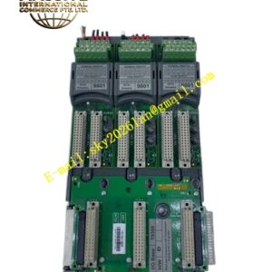
Structural Features Horizontal DIN‑rail snap‑in mounting structure. Rear side SmartSlot high‑density system connector. Front‑side two‑row screw terminal blocks for field cables. Small LED indicator bank at upper‑right section. Internal partition structure separates power circuit and signal circuit. Metal reinforcing brackets for connector mechanical stress relief.
Working Principle Receives control signals from TMR output modules through SmartSlot back‑plane connector. Routes each signal to independent screw‑clamp field terminals. Built‑in surge‑suppression components absorb transient interference from field side. Isolation barriers separate five channel groups. Field power status LED samples field supply voltage and provides visual status feedback for maintenance personnel.
Installation Requirements Mount on standard 35 mm DIN‑rail inside control cabinet. Maintain minimum 15 mm clearance above and below unit for air circulation. Ensure cabinet protective earth ground connection for cabinet rail. Route field signal cables separately from high‑power AC power cables. Torque all screw terminals according to official specification values. Confirm correct SmartSlot mating with matched T8451, T8461 or T8480 output modules.
Usage Notes Do not apply field voltage exceeding rated 24VDC range to terminals. Check terminal screw tightness periodically in high‑vibration cabinet environments. Do not disassemble plastic housing during operation. Replace complete FTA unit when circuit board damage occurs. Verify group isolation integrity after wiring modification. Avoid condensation and corrosive gas inside installation cabinet.