Description
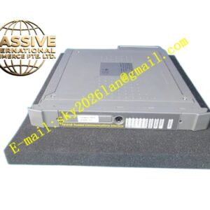
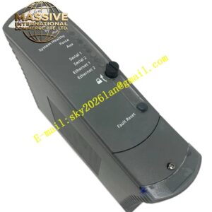
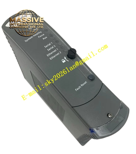
ICS Triplex T8226
Technical Specifications & Performance Parameters:
- DC Input Range: 20 VDC ~ 30 VDC dual‑redundant input
- Nominal Input Voltage: 24 VDC
- DC Output: Regulated 24 VDC
- Rated Output Power: 250 W
- Maximum Output Current: 10.4 A
- Output Voltage Accuracy: ±1 %
- Minimum Hold‑up Time: 1 ms
- Internal Fuse: 20 A, 250 V slow‑blow internal fuse
- Protection Mechanisms: Reverse‑polarity protection, over‑current protection, over‑voltage protection, over‑temperature protection
- Safety Certification: TÜV IEC 61508 SIL 3, UL, CE
- Vibration Resistance: 10‑55 Hz, ±0.15 mm displacement continuous operation
- Shock Resistance: 15 g half‑sine operating shock tolerance
- Operating Temperature: ‑20 °C ~ +60 °C
- Storage Temperature: ‑40 °C ~ +85 °C
- Ambient Humidity: 5 %‑95 % RH non‑condensing
- Weight: 3.20 kg
- Form Factor: Standard Trusted rack plug‑in ruggedized module
Functional Features:
- Dual‑isolated DC input channels, automatic load‑sharing redundant power merging
- Support N+1 parallel redundant operation with active current‑sharing mechanism
- Hot‑swap support for online module replacement without rack power‑supply interruption
- Reinforced mechanical structure for high‑vibration and high‑shock industrial environments
- Comprehensive real‑time diagnostics, detect input loss, output over‑load, reverse‑polarity wiring and internal over‑temperature
- Front‑panel LED indicators show input channel status, output running status and fault‑alarm events
- Timestamped fault‑event upload to system fault historian via IMB backplane bus
- Internal slow‑blow fuse provides hardware‑level fault‑current cutoff protection
Working Principle: Two independent 24 VDC DC power sources feed into T8226 dual input terminals. Internal power‑OR‑ing circuit merges redundant input power. Regulator circuit generates stable 24 VDC output to rack backplane power rail. Parallel‑connected T8226 modules evenly distribute total load current via active current‑sharing control logic. Internal monitoring circuit continuously samples electrical and thermal operating parameters. Fault condition triggers hardware protection and timestamped fault‑alarm output. Ruggedized mechanical assembly maintains stable electrical connection under continuous vibration impact. Single DC input path or single module failure under N+1 configuration cannot break rack power‑supply output.
Material Composition & Structural Characteristics:
- Housing: Extra‑thick die‑cast aluminum alloy shell with vibration‑damping reinforcement structure
- Circuit substrate: Multi‑layer FR‑4 high‑strength industrial printed circuit board, adopt anti‑vibration component soldering process
- Backplane connector: Gold‑plated heavy‑duty anti‑vibration industrial connector with locking reinforcement
- Front panel: Flame‑retardant high‑impact PC engineering plastic with LED indicator window, IP20 protection grade
- Plug‑in card‑type ruggedized structure for Trusted rack dedicated power‑supply‑slot installation
Installation Requirements:
- Insert T8226 module into dedicated power‑supply slot of Trusted main or expander rack chassis, fully tighten front‑panel locking screws
- Dual DC input connect to two independent upstream 24 VDC power‑supply units
- Complete accurate total‑load calculation before deploying N+1 parallel redundant configuration
- DC power wiring adopt high‑strength shielded power cables, fix cable terminals with anti‑loosening fasteners
- Cabinet protective ground resistance ≤4 Ω
- Maintain unobstructed air‑flow clearance around modules for heat dissipation
- When installed on offshore‑type cabinet, apply additional cabinet‑level vibration‑damping measures
Application Scenarios:
- Off‑shore oil‑gas platform Trusted safety‑system rack redundant DC power supply
- Mobile process equipment high‑vibration safety‑control cabinet power‑distribution unit
- Petrochemical field skid‑mount heavy‑vibration safety‑instrumented‑system power source
- On‑shore plant high‑shock mechanical‑equipment associated safety‑interlock rack power supply
- Marine‑type industrial safety‑control system fault‑tolerant DC power infrastructure
Usage Notes:
- Hot‑swap operation only permitted when remaining redundant modules can fully bear total rack load
- Module shell disassembly is forbidden; internal high‑current circuits and internal fuse exist
- Strictly avoid reverse‑polarity DC input connection during field wiring
- After module replacement, verify dual‑input switching performance, parallel current‑sharing function and all diagnostic‑items
- Operate strictly within rated operating temperature, vibration and shock specification limits
- Periodically inspect DC input terminal anti‑loosening fastener condition and cabinet ventilation status