Description
ICS Triplex T8403C
Technical Specifications
| Parameter | Specification |
|---|---|
| Model | T8403C |
| Brand | ICS Triplex (Rockwell Automation) |
| Product Series | Trusted TMR System |
| Module Type | Digital Input Module |
| Input Channels | 40 discrete input channels |
| Input Voltage | 24 VDC |
| Processor Type | 32-bit internal processor |
| Clock Speed | 200 MHz |
| Memory | 16 MB RAM / 8 MB Flash Memory |
| Operating Temperature | -5°C to +60°C |
| Power Consumption | Sourced via internal chassis backplane power rails |
| Communication Protocols | Ethernet, Serial, Modbus RTU |
| Maximum System Capacity | Up to 1024 I/O points per node cluster |
| Controller Redundancy | Hardware link scaling up to 32 controllers |
| Safety Rating | SIL 3 capable (in TMR configurations) |
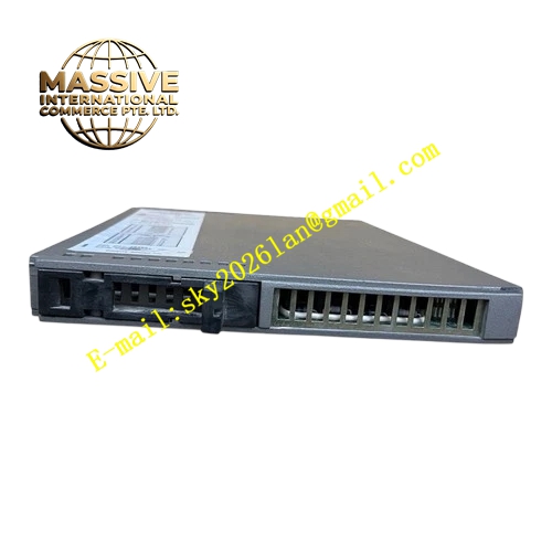
| Dimensions | Standard form factor for Trusted chassis slots |
Functional Features
- High Channel Density: 40 channels per module consolidate I/O and reduce cabinet footprint
- Trusted TMR Architecture: Internal fault-tolerant design aligned with the Trusted platform for high availability
- Online Replacement (Hot-Swap): Module replacement during operation minimizes process interruptions
- Detailed Per-Channel Diagnostics: Channel status and module health feedback enable quicker troubleshooting
- Line Monitoring: Detects open and short circuit conditions on field circuits with proper termination
- Galvanic Isolation: Isolation between field and logic circuits protects the controller and reduces noise coupling
- High-Speed Processing: 32-bit processor at 200 MHz ensures rapid state detection and response
Application Scenarios
- Emergency Shutdown (ESD) system input acquisition
- Fire & Gas (F&G) detector signal monitoring
- Safety interlock switch status detection
- Limit switch and proximity sensor interfaces
- Manual pushbutton and selector switch inputs
- Motor starter auxiliary contact monitoring
Performance Parameters
- Input Response Time: High-speed detection of state changes for safety-critical applications
- Diagnostic Speed: Real-time monitoring of field circuit integrity
- System Scalability: Supports up to 1024 I/O points per node cluster
- Fault Tolerance: TMR architecture prevents false trips from single-channel failures
Material Composition
- Enclosure: Ruggedized industrial housing for harsh environments
- Circuit Board: High-reliability multilayer PCB
- Input Protection: Overvoltage and transient protection circuits on each channel
- Connectors: Industrial-grade backplane and field connectors
Structural Characteristics
- Standard Chassis Slot: Fits into standard Trusted I/O chassis
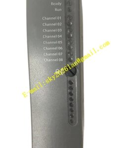
- Front-Panel LEDs: Status indicators for channel states and module health
- Compact Design: High-density packaging maximizes I/O capacity per rack
- Hot-Swap Guides: Mechanical guides facilitate online replacement
Working Principle
The T8403C continuously scans all 40 input channels through three independent input circuits per channel. Each channel state is read simultaneously by three redundant paths. The internal processor compares the three readings and applies 2oo3 voting to determine the final input state. Field-side line monitoring circuits detect wiring faults such as open circuits or short circuits, reporting these conditions to the main processor for alarm generation.
Installation Requirements
- Install in a Trusted I/O chassis with proper seating in the backplane connector
- Use shielded cables for field wiring in electrically noisy environments
- Configure termination resistors for line monitoring functionality
- Ensure chassis power meets specifications before installation
- Follow ESD protection procedures during handling
Operating Precautions
- Verify proper seating of the module in the backplane connector
- Monitor channel LEDs for abnormal indication
- Maintain spare modules for rapid replacement of failed units
- Perform periodic testing of line monitoring circuits
- Ensure field devices provide compatible 24 VDC signal levels