Description
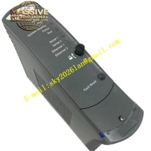
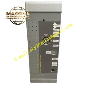
ICS Triplex T8451
Technical Specifications
- Output Channels: 40 digital output channels
- Independent Power Groups: 5 groups of 8 outputs each
- System Supply Voltage Range: 20 to 32 VDC
- Operational Output Voltage Range: 18 to 32 VDC
- Output Current Rating Continuous: 2 Amps per channel, limited to 8 Amps per power group
- Minimum On-State Load Current: 50 milliamperes
- Output On-State Resistance: 0.6 Ohms
- Output Off-State Resistance: 33 Ohms effective leakage
- Output Turn-On/Off Delay: 0.5 milliseconds
- Sample Update Time: 0.5 milliseconds
- Sequence of Events Resolution: 1 millisecond
- Self-Test Interval: 2 minutes
- Field Common Isolation Sustained: Plus or minus 250 VDC
- Field Common Isolation Maximum Withstand: Plus or minus 2.5 kVDC
- Channel to Channel Crosstalk: Greater than minus 40 dB
- Power Consumption: 24 Watts system supply plus 24 Watts field supply at 1 Amp per channel
- Operating Temperature: Minus 5 degrees Celsius to plus 60 degrees Celsius
- Dimensions: 300 millimeters by 30 millimeters by 241 millimeters
- Weight: 1.13 kilograms
Functional Features
- Fault-tolerant fully triplicated output circuitry
- Optional line monitoring per channel to detect open circuit and short circuit field wiring faults
- Electronic latching short circuit protection on each channel
- Sequence of Events reporting with 1 millisecond resolution
- Independent power groups isolating faults to limited channel sets
- Comprehensive automatic diagnostics and self-test every 2 minutes
Application Scenarios
- Emergency shutdown valve control
- Fire and gas system actuation
- Turbine trip solenoid driving
- Motor starter control in safety systems
- Alarm and annunciator activation
- Burner management system outputs
Performance Parameters
- 2 Amp continuous current per channel supporting high-power field devices
- 0.5 millisecond output response time for fast actuation
- 1 millisecond event resolution for accurate sequence recording
- Plus or minus 250 VDC sustained isolation protecting system electronics
Material Composition and Structure
- Industrial-grade steel and aluminum chassis
- Conformal coated circuit boards
- Heavy-duty output transistors with thermal protection
- Isolation barriers rated for 2.5 kVDC
- Front panel LEDs for status indication
Working Principle Each output channel contains three independent output paths that vote on the commanded state. The module receives output commands from the TMR processor, validates them through internal voting, and drives the field device. Line monitoring circuits verify wiring integrity by detecting open and short circuits. Short circuit protection latches off affected channels to prevent damage, requiring manual reset after fault clearance.
Installation Requirements
- Install in Trusted TMR chassis with proper slot alignment
- Connect 24 VDC field power within 18 to 32 V range
- Observe 8 Amp maximum per power group limitation
- Use appropriate wire gauge for 2 Amp per channel
- Ensure minimum 50 milliampere load current for proper line monitoring
Operating Precautions
- Do not exceed 8 Amps per power group
- Verify field device current requirements are within 2 Amp per channel
- Monitor electronic short circuit protection latching status
- Maintain minimum 50 milliampere load for line monitoring functionality
- Replace modules with persistent fault indications promptly