Description
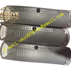
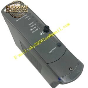
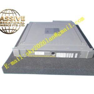
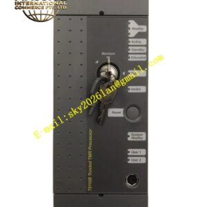
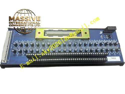
ICS Triplex T8800
Technical Specifications & Performance Parameters:
- Power Supply: 20‑32 V DC backplane power supply, nominal 24 V DC
- Channel Quantity: 40 digital input channels
- Input Signal Level: 24 V DC discrete input signal
- Per‑channel Input Current: 2‑6 mA
- Response Time: ≤10 ms per channel
- Operating Temperature: ‑20 °C ~ +60 °C
- Storage Temperature: ‑40 °C ~ +85 °C
- Safety Certification: TÜV IEC 61508 SIL 3
- Power Consumption: 14 W maximum
- Weight: 0.98 kg
- Form Factor: Standard 3U rack plug‑in module
Functional Features:
- TMR triple‑redundant input sampling circuit for each channel, single sampling‑path failure will not lose signal acquisition
- Channel‑level diagnostic capability, detect abnormal input circuit status
- Hot‑swap support for online module replacement
- Front‑panel LED array indicates each channel input status, module running status and fault alarm
- Time‑stamped fault event upload to system fault historian
- Galvanic isolation between field input circuit and internal safety bus
- Support high‑speed SOE event capture for field digital input signal change
Working Principle: Field 24 V DC switch signal accesses module input channel. Three independent sampling circuits collect same field signal status simultaneously. Hardware voting circuit confirms valid digital input state. Signal status converts into digital data and transmits to safety processor via inter‑module bus. Module captures the exact time of signal state change for SOE recording. Single sampling‑circuit failure is isolated automatically, channel still outputs correct signal status after voting processing.
Material Composition & Structural Characteristics:
- Housing: Aluminum alloy anti‑interference shell
- Circuit board: Multi‑layer FR‑4 PCB with optocoupler isolation components
- Connector: Gold‑plated backplane connector, field‑signal high‑density terminal block
- Front panel: Flame‑retardant plastic with LED indicator window, IP20 protection grade
- Card‑type plug‑in rack‑slot structure
Installation Requirements:
- Insert into I/O slot of Trusted main rack or expander rack, lock front‑panel fixing screws
- Field digital input cables use shielded cables, separate wiring from high‑voltage power cables
- Cable shielding layer single‑end grounded at cabinet ground bar
- Cabinet protective ground resistance ≤4 Ω
- Maintain good ventilation heat‑dissipation inside cabinet
- Field input signal voltage shall strictly stay within 24 V DC rated range
Application Scenarios:
- Limit‑switch and emergency‑stop switch signal acquisition for petrochemical ESD system
- Fire‑detector and gas‑detector switch‑signal input for fire‑gas safety system
- Interlock switch signal collection of chemical plant reactor safety system
- Equipment status switch‑signal input for power‑plant safety instrumented system
- Field safety switch signal acquisition for offshore oil‑gas platform
Usage Notes:
- Hot‑swap operation only under normal system health status
- Do not disassemble module housing
- Prevent over‑voltage surge from field‑side entering input terminals
- After module replacement, verify channel signal acquisition and SOE time‑stamp function
- Do not operate outside rated temperature range
- Regularly check field switch contact and cable insulation condition