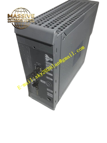
Description
ICS Triplex TC‑215‑01‑4M5
Technical Specifications Cable length: 4.5 m; rated voltage: 300 V; operating temperature range: ‑40 °C ~ +70 °C; overall copper‑braided shielding layer; dual‑twisted differential signal conductors; heavy‑duty metal‑shell connectors with mechanical locking latches; designed for cabinet‑only static routing.
Functional Features Factory pre‑crimped connectors with fixed pin mapping; twisted‑pair structure suppresses signal crosstalk; reinforced strain‑relief structure resists cabinet‑vibration fatigue; mechanical lock prevents accidental disconnection under vibration; full‑coverage shielding suppresses electromagnetic interference inside control cabinet; consistent conductor color coding simplifies later maintenance and troubleshooting.
Application Scenarios Internal signal interconnection between Trusted controller chassis and T8300 expander chassis; connection between T8312 interface adapters; ESD emergency shutdown system cabinet‑internal wiring; safety instrumented system assembly for petrochemical and refinery plants.
Performance Parameters Shield coverage rate greater than 85 %; gold‑plated pin contact resistance less than 9 mΩ; insulation resistance greater than 1000 MΩ; connector mating life reaches 500 cycles; fully compliant with SIL 3 system cabling requirements.
Material Composition Tinned stranded copper conductors, cross‑linked polyethylene insulation, copper‑braided shielding mesh, abrasion‑resistant PUR outer jacket, zinc‑alloy die‑cast metal connector housing, gold‑plated signal contact pins, injection‑molded rubber strain‑relief components.
Structural Characteristics Heavy‑duty rectangular metal‑shell connectors installed at both ends of cable; differential signal pairs independently twisted; injection‑molded strain‑relief treatment at cable‑connector transition section; strictly defined pin‑out matching Trusted hardware port definitions.
Working Principle Transmits multi‑channel digital and analog safety signals between TMR modules, chassis and termination units. Twisted‑pair construction offsets electromagnetic‑induction noise. Continuous shielding diverts external interference to cabinet protective ground. Fixed factory pin‑assignment eliminates human‑caused signal‑loop mis‑connection.
Installation Requirements For static installation inside temperature‑controlled cabinets only; minimum static bending radius equals ten times cable outer diameter; reserve slack length without tensile stress on conductors; fasten connector mechanical latches after insertion; cable shield connects to cabinet protective‑ground bar at single end; maintain sufficient physical separation from high‑power power cables.
Usage Notes Never pull cables by connector housings during handling; prevent cabinet sharp metal edges from damaging outer jacket; verify full model match before connector insertion; do not cut, strip or re‑process factory‑terminated connectors; inspect pins for bending or deformation before power‑on; avoid oil mist and corrosive‑gas accumulation zones inside cabinets.