Description
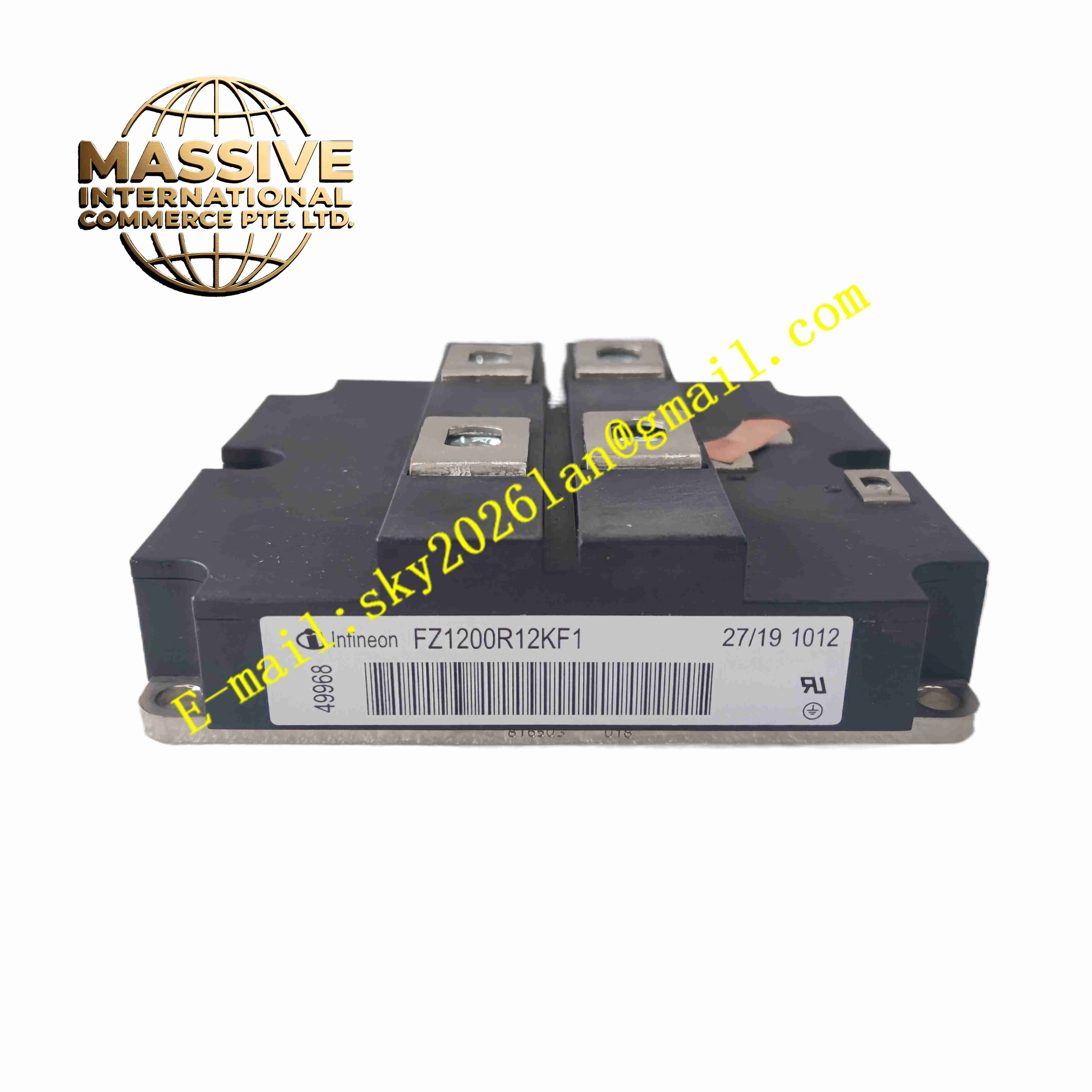
Infineon FZ1200R12KF1
Technical Specifications
- Product Type: IGBT power module
- Collector-Emitter Voltage VCES: 1200 V
- Nominal Collector Current IC: 1200 A at 80 °C case temperature
- Gate-Emitter Voltage VGE: ±20 V
- Internal Diode: Integrated freewheeling diode
- Isolation Voltage: 2500 V AC
- Case Operating Temperature: -40 °C to +125 °C
- Storage Temperature: -40 °C to +150 °C
- Thermal Resistance: Low thermal resistance base plate for heat sink mounting
- Package Type: Industrial high power isolated module package
Functional Features
- High current 1200A IGBT chipset for high power energy conversion.
- Integrated freewheeling diodes handle inductive load return current.
- Isolated metal base plate allows direct mounting to grounded heat sink.
- Low switching loss supports medium frequency inverter operation.
- High short circuit withstand time provides circuit fault tolerance.
- Low thermal resistance transfers heat efficiently to external heat sink.
- Bond wire and chip packaging optimized for high vibration industrial environment.
- Parallel capable design supports multiple modules for higher power rating.
- Stable threshold voltage guarantees consistent switching performance.
- RoHS compliant lead-free package construction.
Application Scenarios
- Medium voltage industrial heavy-duty AC motor drives
- Grid tied solar and wind power inverter systems
- UPS uninterruptible power supply high power unit
- Electric traction and marine propulsion power converter
- Industrial plasma and high power induction heating equipment
Material Composition
- Base plate: Copper metal base with insulating ceramic substrate
- Semiconductor chips: Silicon IGBT chips and silicon freewheeling diode chips
- Bonding material: Aluminum bond wires for chip interconnection
- Encapsulation: Silicone gel encapsulant
- Housing: High temperature resistant plastic housing
- Terminals: Copper alloy power terminals with nickel plating
Structural Characteristics
- Rectangular high power module package with flat copper base plate.
- High current screw type main power terminals for DC and AC connection.
- Small signal gate screw terminals for gate drive signal wiring.
- Ceramic isolation layer between copper base plate and power chips.
- Silicone gel encapsulation protects chips and bond wires from moisture and contamination.
- Flat base plate surface for close contact with heat sink.
Working Principle Gate drive circuit applies positive voltage to gate terminal to turn IGBT on. Current flows from collector to emitter through silicon chip. When gate voltage drops to negative level, IGBT turns off and blocks high collector-emitter voltage. Inductive load current flows through integrated freewheeling diode during switching off period. Heat generated during switching and conduction transfers through ceramic substrate and copper base plate to external heat sink. Gate signal controls turn-on and turn-off timing to generate AC output waveform from DC bus voltage.
Installation Requirements
- Mount module on liquid cooled or forced air heat sink.
- Apply thin layer of thermal grease evenly between module base plate and heat sink.
- Tighten mounting screws to specified torque in cross sequence.
- Use insulated gate drive power supply and gate drive circuit.
- Use high current copper busbar for main power terminal connection.
- Keep gate signal wiring short and shielded to reduce noise interference.
- Perform insulation resistance test before applying high DC bus voltage.
Usage Notes
- Use gate drive circuit with proper negative bias to avoid false turn-on.
- Do not exceed maximum rated collector current and junction temperature.
- Protect module with fast fuses or current limiting circuit for short circuit fault.
- Keep module storage environment dry and use anti-static protection for gate terminals.
- Do not touch power terminals when DC bus capacitor remains charged.
- Check thermal grease condition periodically during long time operation.
- Replace module immediately when chip breakdown or package cracking occurs.