Description
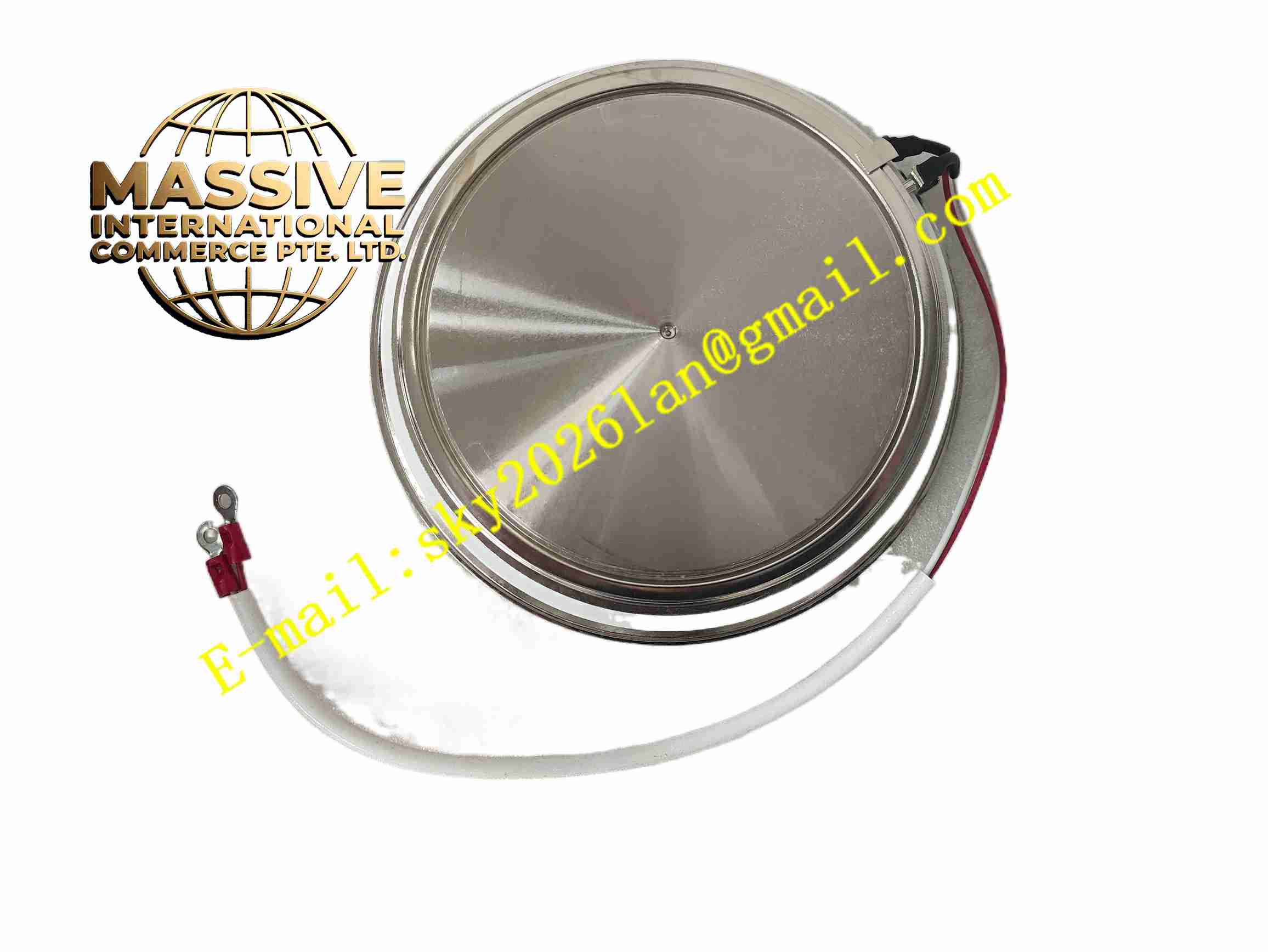
IXYS T2400GB45E
Technical Specifications Repetitive peak off-state voltage 4500V; RMS on-state current 2400A; Gate trigger characteristics defined; Operating junction temperature range -40°C to +125°C; Screw terminal connection; Isolated metal baseplate; Ceramic insulation layer; Power module package form.
Functional Features High surge current withstand capability; Low on-state voltage drop reduces conduction power loss; Isolated baseplate simplifies heat sink assembly; High dv/dt and di/dt rating; Stable gate triggering characteristic; High thermal cycling resistance; Robust structure for industrial power cabinet installation.
Application Scenarios High power AC drive soft starter; Grid-connected rectifier cabinet; Heavy-duty welding power supply; Large industrial furnace power regulator; Hydroelectric excitation control system; Energy storage bidirectional power conversion unit.
Performance Parameters On-state voltage maintains low value under full rated current; Gate trigger current and voltage keep consistent; Junction thermal resistance meets design index; Blocking leakage current stays at low level under rated voltage; Module withstands repeated surge current impact.
Material Composition Copper baseplate; Aluminum nitride ceramic insulating substrate; Silicon thyristor die; Aluminum bonding wires; Silicone gel encapsulation; Epoxy resin outer housing; Copper screw terminals.
Structural Features Rectangular flat power module structure; Metal baseplate for thermal conduction; Internal ceramic insulation separates power die from baseplate; Copper bonding wires connect chip and terminal; External heavy-duty screw terminals for high current wiring; Fully encapsulated internal cavity to protect semiconductor chips.
Working Principle When gate receives trigger pulse signal, the thyristor turns on and conducts large current between anode and cathode. The thyristor maintains conduction status as long as forward current stays above holding current. The device turns off automatically when forward current drops below holding current during AC cycle zero crossing. Heat generated during conduction transfers through ceramic substrate and copper baseplate to external heat sink.
Installation Requirements Mount module on qualified heat sink with thermal grease coated evenly; Apply specified torque to mounting screws; Use high-current copper busbar for power terminal connection; Control heat sink temperature within rated range; Implement reliable protective earthing for heat sink.
Precautions for Use Keep gate drive circuit isolated from high voltage power circuit; Do not exceed repetitive peak off-state voltage; Prevent electrostatic damage to gate terminal before installation; Check torque of mounting screws after thermal cycling; Avoid moisture condensation on module surface in cabinet.