Description
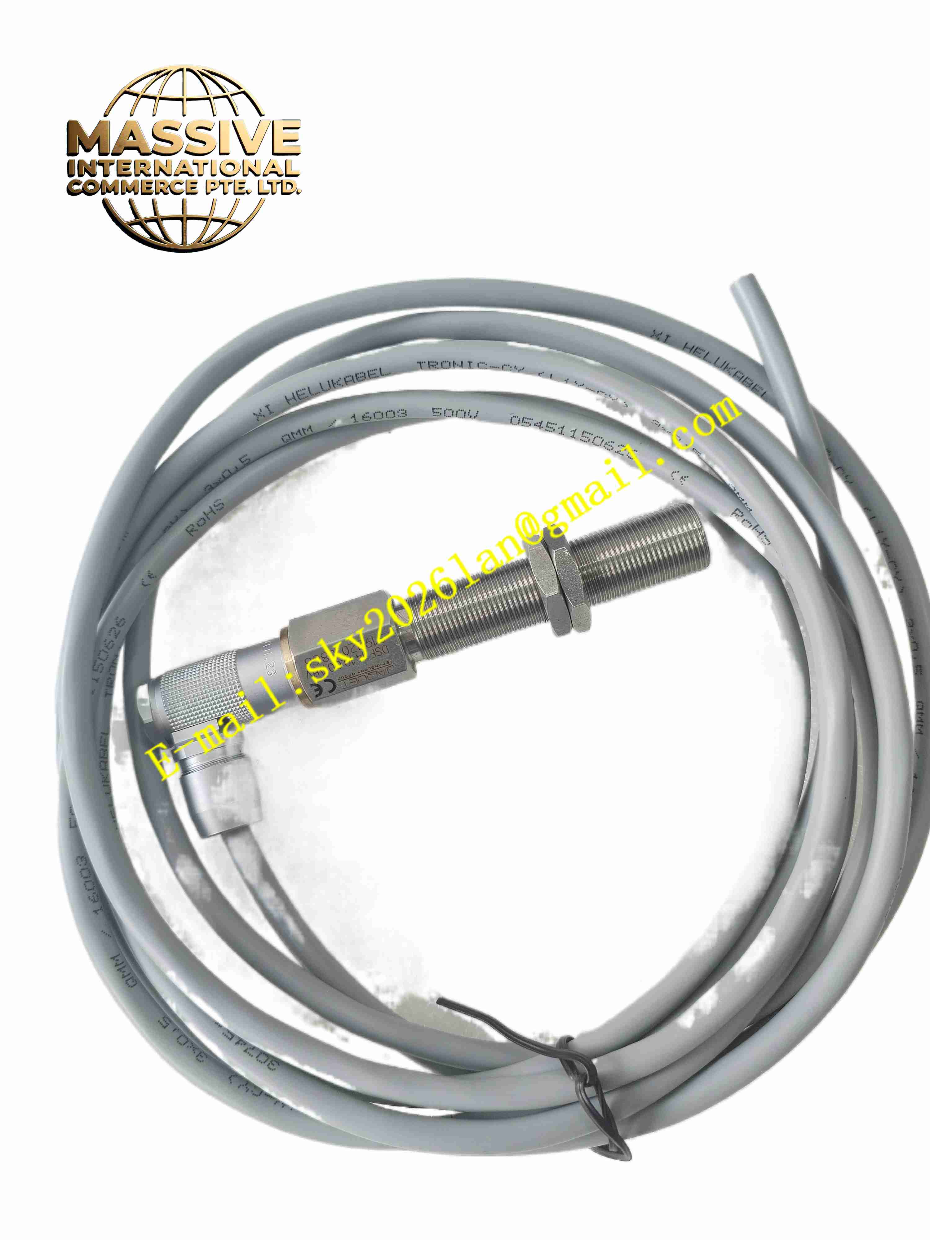
JAQUET DSF1410.00 AHV
Technical Specifications
- Product Type: Hall effect rotational speed sensor
- Sensing Principle: Magnetically biased Hall element
- Output Type: Short-circuit protected pulse output
- Minimum Detectable Frequency: 0.05 Hz
- Certification: ATEX II 2G Ex ia IIC T6 Gb
- Power Supply: Two-wire loop powered
- Housing Material: Stainless steel
- Operating Temperature: -40 °C to +125 °C
- Protection Class: IP67
- Thread Specification: M18 threaded housing
- Connector Type: Industrial circular connector
Functional Features
- Single channel Hall effect sensing, stable pulse output at extremely low rotating speed.
- Intrinsically safe design certified for explosive gas hazardous zones.
- Built-in short-circuit protection for output circuit.
- Stainless steel housing resists vibration, mechanical impact and corrosion.
- Wide operating temperature range adapts to engine and turbine high-temperature environments.
- No magnetic drag effect on the measured rotating pole wheel.
- Long service life with no wearing moving parts.
- Suitable for continuous 24-hour operation on critical rotating equipment.
- High resistance to electromagnetic interference from surrounding power equipment.
- Simple two-wire wiring reduces field installation workload.
Application Scenarios
- Gas turbine and steam turbine speed monitoring and overspeed protection
- Generator shaft rotational speed measurement
- Marine engine speed detection
- Compressor and pump shaft speed monitoring
- Explosive process plant rotating machinery safety interlock
Material Composition
- Sensor housing: Machined stainless steel
- Sensing element: Hall effect chip with bias magnet
- Internal circuit board: High-temperature resistant FR4 PCB
- Cable: Oil-resistant, flame-retardant shielded cable
- Connector: Nickel-plated metal circular connector
- Sealing parts: Fluorosilicone O-ring for high temperature resistance
Structural Characteristics
- Cylindrical M18 threaded metal housing for direct mounting on machine casing.
- Front sensing head with Hall chip and permanent bias magnet.
- Internal electronics fully encapsulated by high-temperature epoxy resin.
- Rear end connected to shielded cable or circular connector.
- All sealing structures achieve IP67 dust and water ingress protection.
- Compact structure can be installed in narrow mounting spaces near rotating shafts.
Working Principle A permanent magnet provides fixed bias magnetic field to the Hall chip. When the ferromagnetic teeth of the pole wheel pass the sensing head, the magnetic flux density changes. The Hall element converts magnetic variation into electrical signal. The internal amplifier shapes the signal into standard pulse waveform. The pulse frequency is directly proportional to the rotational speed of the pole wheel. The connected safety controller calculates real rotational speed by counting pulse frequency.
Installation Requirements
- Install the sensor with correct air gap between sensing head and pole wheel teeth, follow datasheet gap range strictly.
- Align the sensor axis perpendicular to the pole wheel tooth surface.
- Use shielded two-wire cable for signal transmission, single end grounding of shield.
- Fix the sensor firmly with locking nut to prevent loosening caused by machine vibration.
- Keep cable routing away from high-current power cables.
- Complete wiring continuity and insulation test before power on.
- Verify pulse output signal quality at full speed range after installation.
Usage Notes
- Do not scratch or impact the front sensing head surface.
- Maintain the specified air gap, excessive gap will cause signal loss.
- Do not use the sensor beyond the certified hazardous area classification.
- Regularly check cable insulation and connector sealing condition.
- Avoid strong external permanent magnets near the sensing head.
- Do not cut or modify the internal wiring of the sensor.
- Perform speed calibration test after equipment overhaul.