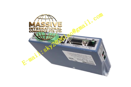
Description
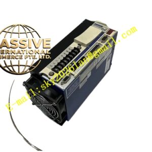
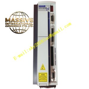
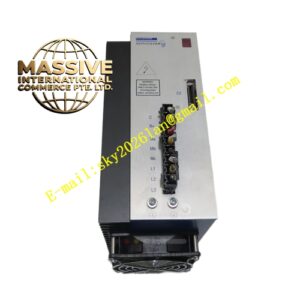
Kollmorgen SERVOSTAR640S64001
Technical Specifications: ‑ Input Power Supply: 3‑phase 208‑480 VAC ‑ Continuous Output Current: 40 A RMS ‑ Peak Output Current: 80 A RMS for 5 seconds ‑ Control Supply Voltage: 24 V DC ‑ Built‑in Communication: CANopen ‑ Optional Expansion Interfaces: PROFIBUS, DeviceNet, SERCOS, SynqNet, EtherCAT ‑ Feedback Support: Resolver, EnDat, HIPERFACE, incremental encoder ‑ Digital Inputs: 6 optically isolated digital inputs ‑ Digital Outputs: 2 optically isolated digital outputs ‑ Analog Inputs: 2 analog inputs ±10 V ‑ Analog Outputs: 2 analog outputs ±10 V ‑ Cooling Method: Forced‑air fan cooling ‑ Installation Form: DIN‑rail cabinet mounting ‑ Operating Ambient Temperature: 0 °C to +55 °C ‑ Storage Temperature: ‑25 °C to +70 °C ‑ Protection Class: IP20 cabinet‑installation‑only ‑ Compliance Certification: CE, UL, RoHS
Functional Features: ‑ High‑power‑stage hardware supports heavy‑load acceleration‑deceleration cycles for large‑frame servo motors ‑ Closed‑loop control for position, velocity and torque operating modes ‑ Built‑in CANopen fieldbus interface for host‑controller connection ‑ Front‑side expansion slot supports plug‑in communication option modules for multiple industrial bus protocols ‑ Compatible with synchronous servo motors and asynchronous induction servo motors ‑ Supports resolver and multiple digital encoder feedback formats ‑ High‑power integrated brake chopper absorbs large‑magnitude regenerative energy from heavy‑load deceleration ‑ Comprehensive fault‑diagnosis function detects over‑current, over‑voltage, under‑voltage, over‑temperature, feedback‑signal loss, motor short‑circuit ‑ Front‑panel LED indicators display operating state, warning and fault codes ‑ Parameter configuration and debugging completed via SERVOSTAR PC software tool ‑ Accepts pulse‑direction command input for compatibility with traditional motion‑controller hardware.
Application Scenarios: Applied for heavy‑duty packaging production lines, large‑format printing presses, heavy‑duty gantry automation equipment, metal‑processing machine‑tool auxiliary axes, material‑test‑bench motion‑control systems. Installed inside industrial control cabinets for general factory‑automation environments.
Performance Parameters: ‑ Current loop bandwidth: Max 3.0 kHz ‑ Velocity loop bandwidth: Max 650 Hz ‑ Position loop bandwidth: Max 200 Hz ‑ Maximum pulse‑direction input frequency: 1 MHz ‑ Short‑circuit protection response time less than 2 μs
Material Composition: ‑ Outer housing: Cold‑rolled steel sheet with black powder‑coated surface ‑ Power‑module substrate: Insulated metal substrate ‑ Power semiconductors: High‑current IGBT power switches ‑ Control‑circuit board: FR‑4 glass‑epoxy printed circuit board ‑ Terminal blocks: Flame‑retardant nylon plastic with tin‑plated copper contacts ‑ Heat‑sink: Large‑size extruded aluminum alloy ‑ Cooling fan: Brush‑less DC cooling fan ‑ Front‑panel cover: Polycarbonate flame‑retardant plastic
Structural Features: ‑ Vertical DIN‑rail‑mount cabinet‑type structure ‑ Physical separation layout for power‑circuit region and signal‑circuit region to suppress electromagnetic interference ‑ Front‑side accessible terminal blocks for power‑supply, motor‑power, feedback‑signal and analog‑digital I/O ‑ Front‑mounted LED‑status‑indicator array ‑ Large‑volume aluminum‑alloy heat‑sink matched with brush‑less forced‑air cooling‑fan ‑ Front‑side expansion slot for plug‑in communication‑option modules.
Working Principle: Three‑phase AC mains input is rectified into DC‑bus voltage inside amplifier. High‑current IGBT inverter converts DC‑bus voltage to adjustable‑frequency adjustable‑amplitude three‑phase AC output for driving heavy‑load servo‑motor. Motor position and velocity feedback‑signal feeds back to drive‑control‑board. Digital‑control chip executes closed‑loop position, velocity and torque algorithm according to set‑point commands from host‑controller or field‑bus. High‑power brake‑chopper consumes regenerative‑energy produced by heavy‑load deceleration to stabilize DC‑bus‑voltage.
Installation Requirements: ‑ Install unit inside closed industrial‑electrical‑cabinet with minimum IP54 protection‑rating. Outdoor‑installation is prohibited. ‑ Mount vertically on standard DIN‑rail. Horizontal or inverted‑mounting‑orientation is forbidden. ‑ Reserve 50 mm vertical‑clearance above and below unit for cooling‑air‑flow. Reserve 20 mm horizontal‑clearance on left‑hand and right‑hand sides. ‑ Connect PE protective‑earth‑terminal firmly to cabinet‑ground‑bus‑bar. ‑ Motor‑cable‑shielding‑layers must connect to dedicated‑shielding‑terminals on drive‑housing. ‑ Maintain minimum 100 mm separation‑distance between high‑power motor‑power‑wiring and low‑voltage signal‑wiring. ‑ 24 V DC control‑power‑supply must provide SELV safety‑extra‑low‑voltage‑output. ‑ Cabinet‑internal‑ambient‑temperature must not exceed +55 °C under continuous‑full‑load‑operation. Verify cooling‑fan normal‑working‑condition after power‑on.