Description
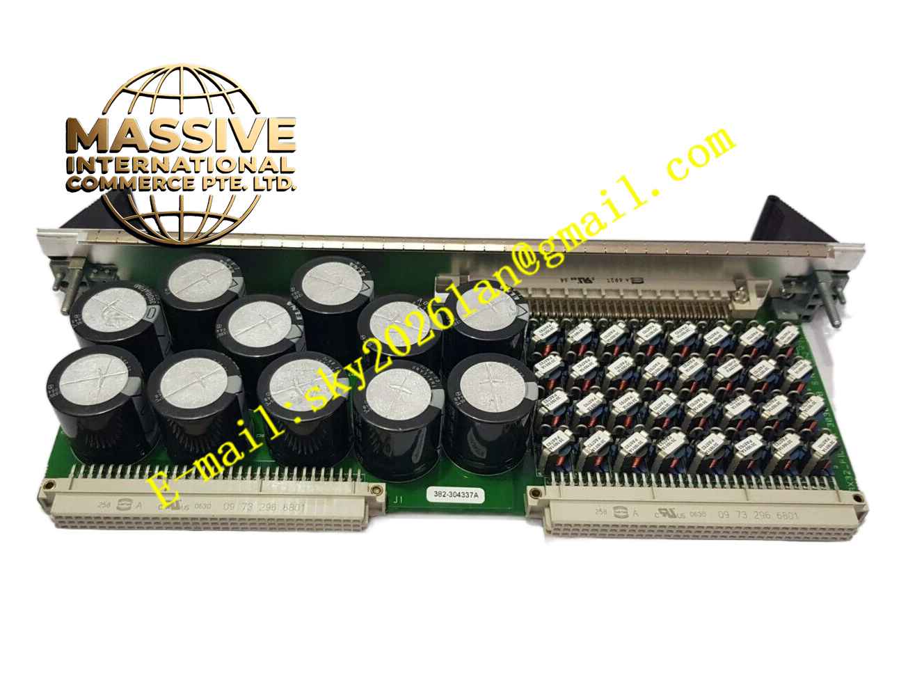
Kongsberg TRX32 303088G
Technical Specifications 32 independent transmit and receive channel pairs; multi-frequency acoustic signal support; Ethernet communication interface for host positioning computer; external synchronization input port; serial debug ports for maintenance and diagnosis; integrated energy storage capacitor bank; onboard fuses for channel overcurrent protection; standard rack plug-in LRU form factor; marine-grade working temperature range; configurable hardware switches and link settings for system matching. Up to eight TRX32 boards can be assembled within a single x81 series transceiver unit.
Functional Features Generates programmable multi-frequency pulse signals to excite each element of the underwater transducer array. Amplifies, filters and digitizes weak acoustic echo signals captured by transducers. Embedded digital signal processing circuits execute real-time signal conditioning and echo detection. Transmits digitized acoustic measurement data to the top-side positioning host over Ethernet. Accepts external synchronization trigger signals to align acoustic pulse transmission with system timing. Provides hardware fault diagnosis for channel overload, power abnormality and communication interruption. Reports board status and channel error information to the HiPAP control software. Supports configuration of signal gain, pulse length and frequency parameters for different subsea operating ranges.
Application Scenarios Ultra-short baseline acoustic positioning for ROV and AUV tracking on offshore drilling platforms. Subsea transponder positioning for offshore pipeline installation and subsea structure survey. Dynamic positioning reference measurement for marine construction vessels. Underwater acoustic survey and seabed mapping operations. Subsea equipment recovery and underwater inspection missions that require high-precision acoustic ranging and bearing calculation.
Performance Parameters High sampling rate for acoustic echo signals; low signal distortion during transmission and reception; high channel isolation to reduce crosstalk between adjacent acoustic elements; fast echo data delivery to positioning host; stable signal output under continuous long-duration operation; strong electromagnetic interference resistance for marine cabinet environments.
Material Composition Main circuit substrate uses FR-4 high-reliability flame-retardant multilayer printed circuit board. Signal processing and digital conversion chips are industrial wide-temperature semiconductors. Energy storage components adopt long-life industrial electrolytic capacitors. Backplane and front panel connectors use gold-plated copper alloy contacts. The shielding and reinforcing cover plate is fabricated from metal alloy. Passive components such as resistors and capacitors are marine-qualified high-stability types.
Structural Characteristics Rectangular rack plug-in board design, equipped with two mechanical ejector latches for secure locking and easy removal. Front panel integrates Ethernet status LEDs, power indicators and I/O status indicators. Front panel carries external synchronization connector and serial debug connectors. A metal screening and reinforcement plate covers the component side of the PCB to suppress electromagnetic interference and provide mechanical protection. Rear edge connector mates with the transceiver unit internal backplane for power supply and data bus connection.
Working Principle The top-side positioning host sends acoustic transmission commands to the TRX32 board through the Ethernet interface. The onboard digital circuit generates coded multi-frequency excitation pulses, which are amplified and sent to corresponding transducer channels to launch acoustic waves into seawater. When acoustic pulses reflect back from subsea transponders, the transducer array converts acoustic energy into weak analog electrical signals. The receive circuit amplifies and filters these analog signals, then converts them into digital samples. Digital signal processing modules extract echo arrival time and phase information from sampled data. Processed measurement data transmits back to the positioning host for calculation of target range and azimuth. The built-in monitoring circuit continuously tracks power, channel current and communication state and triggers fault flags once abnormal conditions emerge.
Installation Requirements Cut off the power supply of the HiPAP transceiver chassis before installing or removing the board. Align the board with the designated slot guide rails and push the board fully into the backplane connector. Lock the two ejector latches to guarantee stable electrical contact. Set hardware switches and jumpers on the board according to the system configuration document. Route transducer coaxial cables separately from high-power cables to avoid interference. Complete Ethernet cable connection between the board and the positioning host network switch. Perform channel gain calibration and synchronization timing verification after installation.
Precautions for Use Implement anti-static protection during all handling and replacement procedures to prevent electrostatic damage to sensitive signal chips. Do not remove the metal shielding cover during normal system operation. Keep the chassis ventilation openings unobstructed to maintain proper thermal dissipation. Do not exceed the rated power and current limits of each acoustic channel. Inspect capacitor banks and fuses regularly during vessel drydock maintenance. Avoid mechanical shock and vibration during transportation and disassembly. Only use Kongsberg official configuration software to modify board working parameters. Disconnect chassis main power and wait for capacitor discharge before opening the transceiver unit enclosure.