



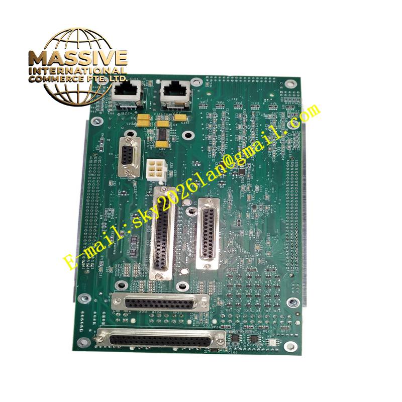
Description
LAM 853-049542-173
Technical Specifications Multiple digital input and output channels; analog signal conditioning circuits; dedicated communication interface matching LAM equipment backplane; 24V DC equipment power supply; designed for cleanroom low-particle environments; wide temperature range suitable for process tool cabinets.
Functional Features Acquires state feedback signals from chamber sensors, limit switches and pressure transducers. Outputs drive signals to solenoid valves and auxiliary actuators to control chamber gas flow and wafer transfer movements. Transmits all sampled signals to the main equipment controller and receives execution commands from the host. Built-in circuit protection prevents damage from short-circuited field loads. Reports channel fault status to the equipment fault diagnostic system.
Application Scenarios LAM dielectric etch and semiconductor wafer processing tools in cleanroom semiconductor fabrication facilities.
Performance Parameters Rapid digital signal response; accurate analog signal conditioning; stable signal transmission under cleanroom electromagnetic conditions; low particle emission design.
Material Composition PCB substrate is high-grade FR-4 material compliant with semiconductor equipment standards; signal processing and driver chips are industrial components; connectors use gold-plated contacts suitable for repeated cycling; surface finishes minimize particle shedding.
Structural Characteristics Vertical plug-in board for equipment internal rack; edge gold fingers mate with the machine backplane; front panel with status LEDs for each signal group; pin headers and terminal connectors for field sensor and actuator wiring; fixing brackets secure the board inside the equipment cabinet.
Working Principle Sensor and switch signals enter the board’s input circuits, undergo level conversion and filtering, and are sent to the equipment controller via the backplane bus. Command signals from the controller are received by the board and converted into drive signals to operate solenoids and actuators. The board continuously monitors load conditions and sends fault notifications to the host software.
Installation Requirements Carry out installation inside the semiconductor tool after power lockout. Handle the board in cleanroom conditions with proper anti-static wrist straps. Align gold fingers carefully when inserting into the backplane. Verify all sensor and actuator wiring against the equipment electrical schematic before power restoration.
Precautions for Use Strict anti-static rules must be followed at all times. Avoid touching PCB traces and connector pins with bare hands. Prevent process chemicals and particles from contaminating the board surface. Do not operate the board outside the original LAM processing tool.





