



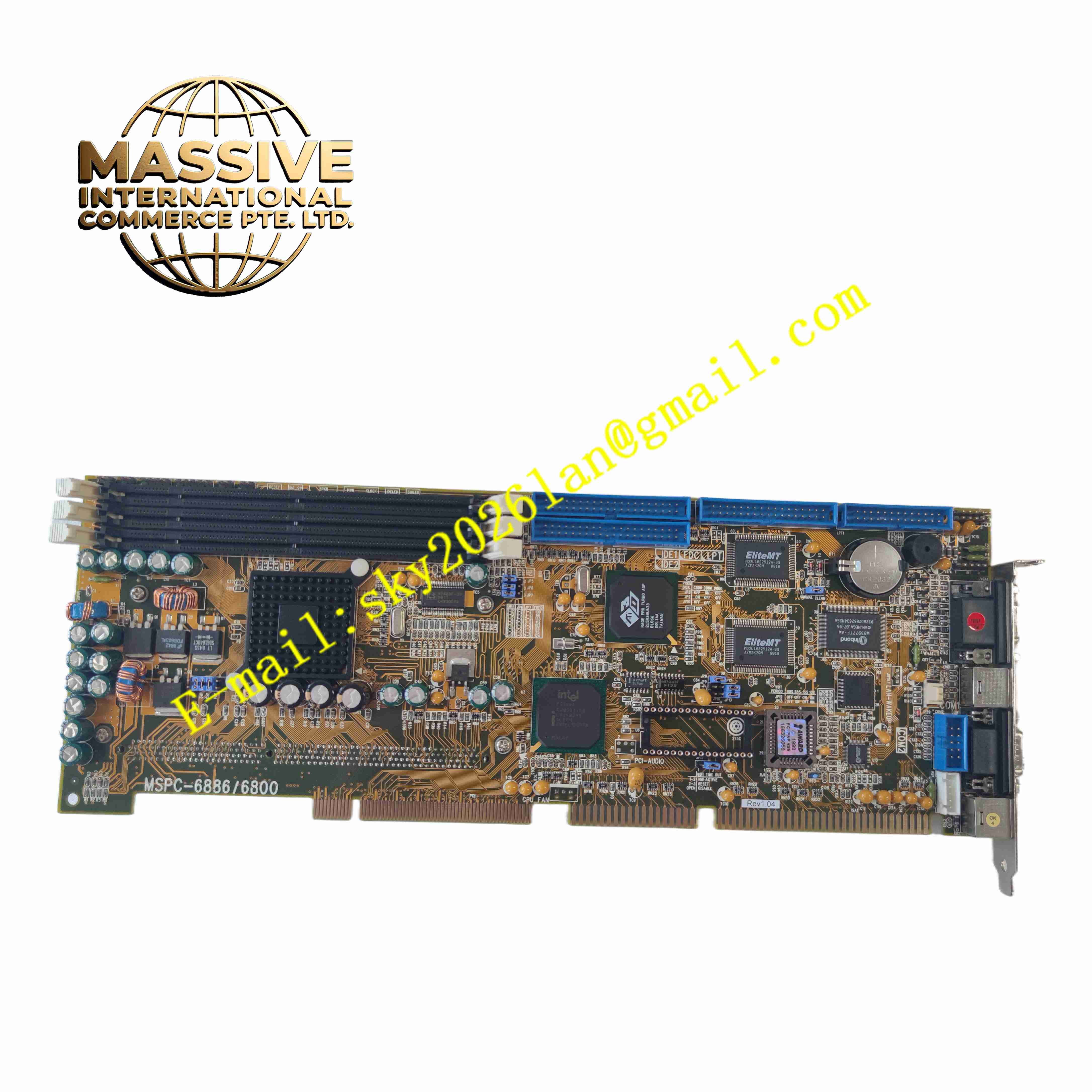
Description
Macrotek MSPC-68866800
Technical Specifications: Operating supply voltage: 5V DC Output voltage: 3.3V Maximum power consumption current: 100mA Working temperature range: -40℃ ~ +85℃ Communication interfaces: RS232, Ethernet, CAN bus Storage: 16KB ROM Memory: 64KB RAM Input and output: Digital DI/DO terminals, analog signal sampling ports Mounting form: PCB circuit board, DIN rail or chassis embedded installation
Functional Features: Supports multi-axis synchronous motion control, electronic cam, electronic gear and positioning control. Built-in overcurrent, overvoltage, undervoltage and overtemperature protection circuits. Supports parameter configuration, online debugging and real-time status monitoring. High-speed pulse output for high-resolution position closed-loop control. Real-time fault diagnosis and fault code output function. Strong anti-electromagnetic interference capability for heavy industrial environment.
Application Scenarios: Automated assembly machines, CNC processing equipment, packaging machinery, material conveying robots, textile automation equipment, semiconductor handling equipment, and customized special automated machinery.
Performance Parameters: Positioning repeatability: Sub-millimeter level under matched servo system. Motion instruction response time: Less than 1 microsecond. Pulse output frequency: Up to 1MHz. Continuous long-running stability: 24-hour uninterrupted operation. Vibration resistance: Meet IEC 60068-2-6 industrial vibration standard.
Material Composition: Main substrate: FR-4 high temperature resistant glass fiber epoxy printed circuit board. Electronic components: Industrial grade resistors, capacitors, high-speed processing IC, optocoupler isolation chips. Connector: Gold-plated copper alloy terminal connectors with PA66 plastic insulation housing. Solder: Lead-free industrial tin solder.
Structural Features: Compact rectangular PCB structure with standard industrial board size. Separate power area, signal processing area and communication interface area on PCB layout. Multiple mounting holes for fixed installation inside control cabinet. On-board indicator LEDs for power, communication and fault status. Removable terminal blocks for convenient field wiring.
Working Principle: The control board receives motion commands from upper host controller via communication port. The on-board processor analyzes and calculates position, speed and torque instructions, then outputs pulse or bus commands to servo drives. It collects real-time position feedback signal from motor encoder, compares feedback value with target value, and adjusts output signal through closed-loop PID algorithm to achieve precise positioning and speed regulation. Built-in protection circuits continuously monitor voltage, current and temperature, and trigger protection action once exceeding threshold.
Installation Requirements: Install inside sealed industrial control cabinet, away from high-voltage power cables and high heat sources. Use copper wire for power wiring, keep power cable and signal cable separated. Secure the board through mounting holes or DIN rail bracket, ensure no mechanical looseness. Ground the cabinet and board grounding terminal to protective earth ground. Maintain ambient air circulation to avoid heat accumulation around the board.
Usage Notes: Cut off power supply before wiring or disassembly. Do not apply voltage exceeding rated 5V DC to power terminal. Prevent conductive dust, metal debris and liquid from entering circuit area. Complete parameter backup before firmware upgrade or parameter modification. Avoid static electricity contact with PCB surface during maintenance, wear anti-static wristband. Check terminal tightness regularly to prevent poor contact caused by vibration.







