Description
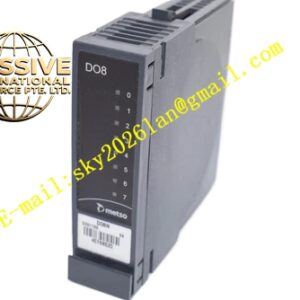
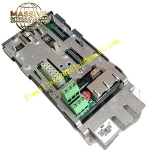
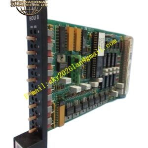
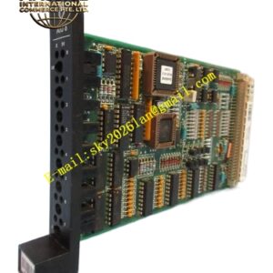
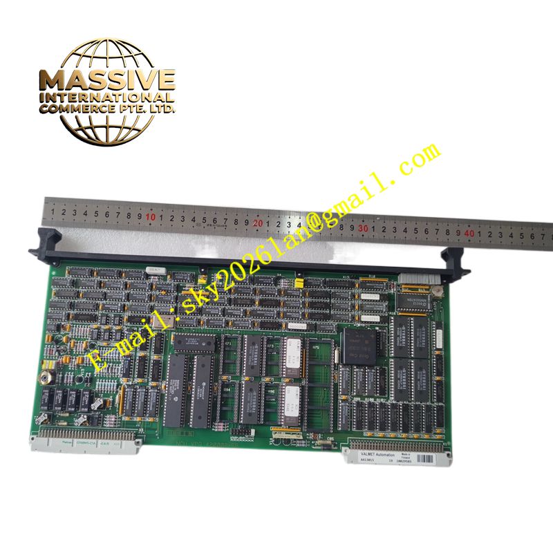
Metso A413015
Technical Specifications Multiple digital output channels; relay or transistor output type; 24V DC control power; channel short-circuit protection; backplane bus communication; rack plug-in installation; individual channel status LED.
Functional Features Receives digital control commands issued by the Metso main controller through the rack backplane. Switches the on-off state of each output channel to drive field actuators. Provides short-circuit and overload protection for every output channel. Reports channel fault information, load abnormal state and communication status to the control system. Supports safe output state setting when communication with the main controller is interrupted.
Application Scenarios Ore crushing and sorting control, pulp mill process valves, paper machine auxiliary equipment control, mineral processing plant DCS cabinets.
Performance Parameters Quick channel switching response; stable load driving capacity; low contact resistance for relay version; reliable fault diagnosis of output loads.
Material Composition Circuit substrate is FR-4 flame-retardant multilayer PCB; drive components are industrial power semiconductors or sealed relays; backplane connector pins are gold-plated copper; front panel shell is flame-retardant thermoplastic.
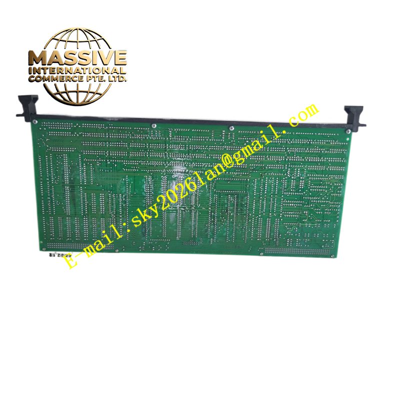
Structural Characteristics Plug-in rectangular card for Metso standard control racks; front panel with independent LED status indicator for each channel; rear gold finger connector for rack backplane connection; built-in locking latch to fix the card in the slot.
Working Principle The main controller sends digital logic commands to the module through the rack backplane bus. The onboard microprocessor decodes the command data and controls each output drive circuit. Transistor or relay components switch the external load circuit on and off. Real-time monitoring circuits detect abnormal current of each channel and feed fault signals back to the control system.
Installation Requirements Power off the control rack before inserting or removing the module. Insert the module into the assigned rack slot and lock the latch. Connect field actuator wiring to the matched terminal base. Configure fail-safe status of each output channel in Metso system configuration software and test channel action.
Precautions for Use Match the output load voltage and current with the module rated parameters. Do not exceed the maximum load capacity of a single channel. Separate field power wiring from signal cables to reduce electromagnetic interference.