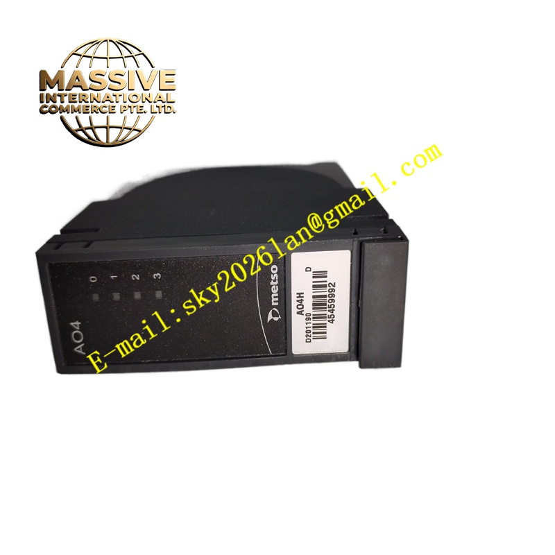
Description
Technical Specifications 4 galvanically isolated analog output channels; signal range 4-20mA; 16-bit digital-to-analog conversion; output accuracy ±0.15% full scale; isolation voltage 1500V AC between field side and backplane; 24V DC auxiliary power supply; operating temperature -20°C to +70°C; IP20 protection rating.
Functional Features Receive digital setpoint values from the rack controller through the backplane bus. Convert digital data into stable 4-20mA current signals for field regulating equipment. Support channel output scaling configuration corresponding to valve stroke and process variable. Detect open circuit and load abnormality of each output loop and send diagnostic alarms to the controller. Provide overcurrent protection for field output terminals. Upload channel status and diagnostic information to the main control unit in real time.
Application Scenarios Ore flotation reagent valve regulation, pulp mill digester steam valve control, mineral crushing feed rate adjustment, tailings pipeline control valve positioning, wastewater treatment chemical dosing valve control.
Performance Parameters Low output signal drift under high vibration and dusty plant environment; high channel isolation to avoid cross interference; stable current output under changing load impedance; fast response to controller setpoint change.
Material Composition PCB substrate adopts FR-4 flame-retardant multilayer printed circuit board; digital-to-analog conversion and drive chips are industrial semiconductors; optocoupler devices realize channel isolation; backplane gold finger contacts use gold-plated copper alloy; module shell is flame-retardant thermoplastic resin; terminal contact springs use nickel-plated copper alloy.
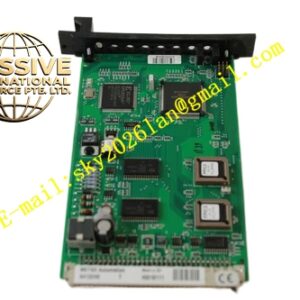
Structural Characteristics Vertical plug-in module for Metso standard control rack. Front panel has power, communication and channel fault LED indicators. Rear gold finger connector connects to rack backplane for power and bus communication. Front screw terminal blocks are used for field actuator wiring. Side mechanical latch locks the module against cabinet vibration.
Working Principle Digital control commands from the main controller pass through the backplane bus to the module onboard processor. The processor sends data to digital-to-analog conversion circuit, which generates analog current signal after isolation and power amplification. The current signal is transmitted to field valve positioner to adjust valve opening. The module monitors output loop load status continuously and reports faults.
Installation Requirements Power off the control rack before module installation or replacement. Insert the module into the target rack slot and lock the side latch. Use shielded twisted-pair cables to connect field valve positioners to module output terminals. Configure output range and scaling parameters in Metso engineering software. Test the full-range output of each channel after power recovery.
Precautions for Use Do not short-circuit output terminals for a long time. Keep analog signal cables away from high-current motor power cables. Maintain single-point grounding of shielding layer. Back up control configuration before module replacement.