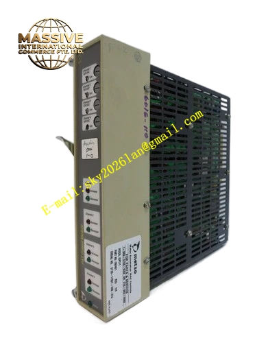
Description
METSO IOP111
Technical Specifications: 16-channel digital input; support passive dry contact signal; backplane bus power supply; rack plug-in installation; operating temperature range 0℃ to +60℃; channel isolation withstand voltage 1500VAC; each channel with independent LED status indicator; protection class IP20.
Functional Features: Collect passive contact switching state; photoelectric isolation between field circuit and system logic circuit; hardware open circuit detection for each channel; complete module self-diagnosis function; single-channel fault isolation without interfering other working channels; upload fault status information to DCS monitoring system.
Application Scenarios: Valve limit signal collection cabinet of thermal power plant auxiliary equipment; equipment running status monitoring cabinet of pulp and paper factory; safety interlock contact collection cabinet of chemical plant; valve feedback signal acquisition cabinet of water treatment system.
Performance Parameters: Signal response time less than 1ms; stable signal identification under strong industrial interference environment; meet industrial EMC electromagnetic compatibility standards; support 7×24 hours uninterrupted continuous operation.
Material Composition: Glass fiber epoxy multilayer PCB circuit board; photoelectric isolation chips; gold-plated edge connector; metal front panel; circuit board coated with three-proof protective coating.
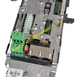
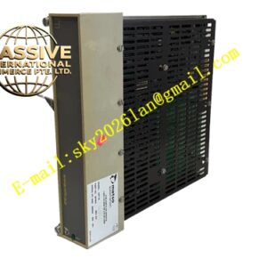
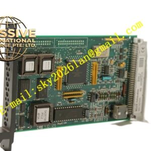
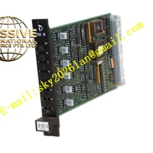
Structural Features: Rack plug-in modular structure; front panel equipped with LED indicators for power, running and channel fault status; rear gold-plated edge connector connects to MaxPAC rack backplane bus; field signal circuit and system logic circuit are physically separated; panel fitted with mechanical locking buckle to prevent loosening caused by vibration.
Working Principle: Field passive dry contact signals are transmitted to IOP111 module through supporting terminal base. Photoelectric isolation components isolate field circuit from DCS system circuit. The module identifies contact open or closed state and converts it into digital logic signal. The digital signal is transmitted to DPU controller via backplane bus. The module continuously detects each channel state and uploads alarm information when circuit fault occurs.
Installation Requirements: Install in designated slot of MaxPAC I/O rack and match with original supporting terminal base. Use shielded cable for switching signal wiring. Signal cables and high-power power cables are laid in separate trunking. Cabinet protective grounding terminal must be connected reliably. Reserve enough ventilation space around module.
Precautions for Use: Cut off field loop power supply before wiring work. Do not access high voltage signal to digital input channel. Cut off rack backplane power before module disassembly. Wear anti-static wristband during operation. Check terminal tightness regularly. Keep cabinet internal humidity within 20%~80% without condensation.