Description
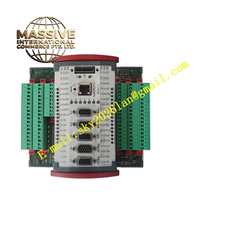
MOOG D136-001-007
Technical Specifications
Brand: MOOG
Product Model: D136-001-007
Product Series: MSC I Motion Controller
Processor: 32-bit PowerPC processor with RISC architecture and floating-point unit
Flash EEPROM: 4 MB (typical data retention period of 10 years)
Dimensions (W × D × H): 160 mm × 170 mm × 85.5 mm (6.30 in × 6.69 in × 3.36 in)
Installation Width: 149 mm / 154.5 mm
Operating Temperature: +5°C to +55°C (+41°F to +131°F)
Storage Temperature: -25°C to +70°C (-13°F to 158°F)
Maximum Average Temperature (24-hour operation): +50°C (+122°F)
Relative Humidity: 10% to 95% (non-condensing)
Maximum Operating Altitude: 2,000 m (6,500 ft)
Maximum Storage/Transport Altitude: 3,000 m (9,800 ft)
Supply Voltage: 24 V DC (18 to 36 V), compliant with SELV standard EN 60950-1
Current Consumption: 0.5 A at no load, 2 A at full load
Certification Standards: CE, UL, RoHS compliant
Functional Features
High-Precision Control: Achieves exceptional accuracy in position (±0.01°), speed, pressure, and force control through advanced digital signal processing and high-speed sampling
Fast Response Speed: Response time of less than 1 ms, enabling rapid tracking of target position and speed changes
Dual-Axis Control: Capable of simultaneously controlling two hydraulic servo-actuators with precise synchronization
PLC Functionality: Integrated programmable logic controller capabilities for implementing complex control logic directly on the controller
High-Resolution I/O: Equipped with 8 analogue inputs (16-bit resolution, configurable as ±10 V, ±10 mA, or 4-20 mA) and 2 analogue outputs (±10 V, configurable as ±10 mA, ±50 mA, or 4-20 mA)
Multiple Communication Interfaces: Supports Ethernet (10 MBit/s), 2× CAN (10 kBit/s to 1 MBit/s), PROFIBUS-DP slave (12 MBit/s), and 2× EIA-232 serial ports
Position Sensor Support: Two sensor interfaces configurable as incremental encoder (max 8 MHz, 4-edge evaluation) or SSI (Gray/binary, 8-32 bits, 78 kHz to 5 MHz)
Digital I/O: 8 configurable digital inputs/outputs (Type 1 per IEC 61131-2) with 0.5 A max current per output
Expansion Capability: Q connectors on both sides support up to 7 additional modules via E-Bus (5-10 MBit/s) and LocalCAN
Comprehensive Protection: Short-circuit protection, thermal overload protection, and overvoltage protection up to ±36 V on all I/O channels
Application Scenarios
Industrial Automation: Machine tools, robotic arms, conveyor systems, and production line automation requiring precise motion control
Aerospace and Defense: Aircraft component control, missile guidance systems, radar tracking systems, and flight simulation equipment
Automotive Industry: Automated production lines, testing equipment, and electric vehicle powertrain control
Energy Sector: Wind turbine pitch control, hydraulic press control, and turbine governor systems
Manufacturing: Injection molding machines, metal forming equipment, and material handling systems
Test and Simulation: Hardware-in-the-loop testing, motion simulation platforms, and structural testing rigs
Marine and Offshore: Ship steering systems, offshore platform crane control, and subsea equipment operation
Performance Parameters
Position Control Accuracy: ±0.01°
Response Time: Less than 1 ms
Control Bandwidth: Suitable for high-dynamic-response applications
Analogue Input Resolution: 16-bit
Analogue Output Resolution: 16-bit
Encoder Interface Max Frequency: 8 MHz
SSI Transmission Frequency Range: 78 kHz to 5 MHz
CAN Transmission Rate: 10 kBit/s to 1 MBit/s
PROFIBUS-DP Transmission Rate: 12 MBit/s
Ethernet Speed: 10 MBit/s (10Base-T)
Reference Voltage Output: +10 V DC, max 5 mA
Material Composition
Industrial-grade printed circuit board with surface-mounted electronic components, 32-bit PowerPC RISC processor chip, precision analogue-to-digital and digital-to-analogue converters, high-quality capacitors and resistors for signal conditioning, robust aluminum or reinforced polymer housing for structural integrity and heat dissipation, gold-plated connector contacts for reliable signal transmission, flame-retardant materials compliant with UL94 standards
Structural Features
Compact modular form factor (160 mm × 170 mm × 85.5 mm) designed for DIN rail or panel mounting, front-panel RJ45 Ethernet connector, two D-Sub connectors for CAN interfaces, side Q connectors for E-Bus expansion, status LEDs for power, communication, and fault indication, integrated heat dissipation features, protective connector covers, clearly labeled terminal designations for easy wiring, rugged enclosure suitable for industrial environments
Working Principle
The D136-001-007 operates as a digital motion controller that receives command signals from a host system or local PLC logic via fieldbus (CAN, PROFIBUS-DP) or serial interfaces. The 32-bit PowerPC processor executes the control algorithm, processing feedback signals from position sensors (incremental encoders or SSI absolute encoders) connected to the sensor interfaces. The controller compares the actual position/speed with the commanded values and computes the required output signal. This output is sent via the high-resolution analogue outputs (±10 V) to drive proportional or servo valves controlling hydraulic actuators. The controller can manage two independent servo axes simultaneously, with the ability to coordinate and synchronize their motion. Digital I/O channels handle discrete signals such as limit switches, emergency stops, and status indicators. The integrated PLC functionality allows users to implement custom logic for sequence control, interlocking, and safety functions. All parameters, control loops, and I/O configurations are set up using MOOG’s MACS software on a PC, connected via the dedicated MACS serial port or Ethernet.
Installation Requirements
Verify the controller is undamaged and all accessories and documentation are complete before installation
Mount the controller securely on a DIN rail or panel using the provided mounting hardware, ensuring the installation width (149/154.5 mm) is accommodated
Ensure adequate ventilation around the controller to maintain operating temperature within +5°C to +55°C
Connect the 24 V DC power supply (18-36 V range) using properly sized wiring, ensuring compliance with SELV standards
Connect fieldbus cables (CAN, PROFIBUS-DP) using shielded industrial-grade cables with proper termination
Connect Ethernet cable to the RJ45 port for communication with host systems or MACS software
Wire analogue and digital I/O connections according to the application requirements, observing polarity and voltage ratings
Connect position sensors (encoders or SSI) to the dedicated sensor interfaces, ensuring correct wiring per EIA-422 standards
Configure all parameters using MACS software before commissioning the system
Ensure proper grounding of the controller and all connected equipment to minimize electrical noise
Usage Precautions
Do not exceed the specified supply voltage range of 18-36 V DC to prevent damage to the controller electronics
Ensure the operating environment temperature remains within +5°C to +55°C; provide additional cooling if necessary
Keep the controller clean and free of dust, oil, and moisture to maintain reliable operation
Use shielded cables for all signal connections to minimize electromagnetic interference
Do not disconnect or connect I/O wiring while the system is powered unless specifically designed for hot-swap operation
Back up all controller configuration and program settings before making changes
Regularly monitor status LEDs and diagnostic messages for early detection of faults
Verify that all connected sensors and actuators are compatible with the controller’s I/O specifications
Handle the controller with care during installation to avoid mechanical shock or electrostatic discharge damage
Refer to the official MOOG documentation for detailed troubleshooting procedures and error code definitions