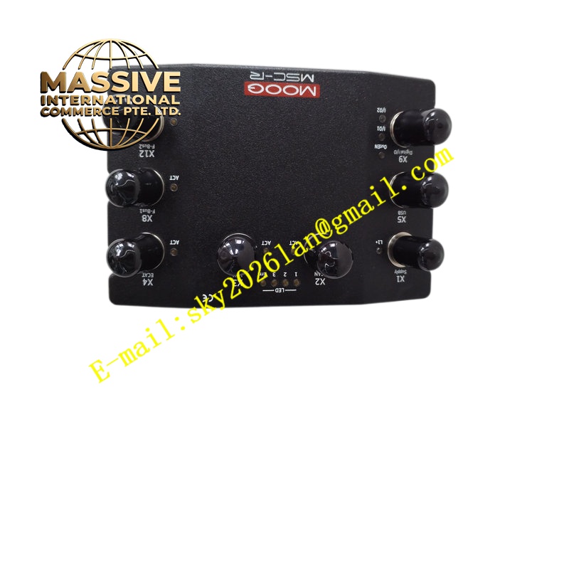
Description
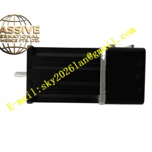
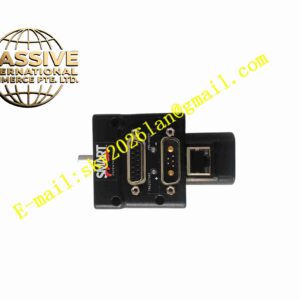
MOOG D765-102-4
Technical Specifications Maximum working pressure for P, A, B, X ports reaches 315 bar; maximum return pressure for T port is 210 bar; ambient operating temperature -20 ℃ to +60 ℃; hydraulic fluid temperature -20 ℃ to +80 ℃; command signal accepts ±10 V DC; built-in spool position monitoring output; hysteresis less than 0.5 %; resolution less than 0.1 %; weight 1.1 kg; protection rating IP65 with fitted electrical connector; vibration resistance up to 30 g along three orthogonal axes.
Functional Features Dual nozzle-flapper pilot stage achieves high bandwidth and low friction; integrated electronic amplifier simplifies external wiring; spool position feedback stabilises valve gain and reduces drift; internal fault monitoring detects loss of command signal and spool blockage; configurable null adjustment for static zero offset correction; fluorocarbon seals support wide-range industrial hydraulic fluids.
Application Scenarios Hydraulic motion simulation platforms, aerospace component vibration test benches, high-speed metal forming equipment, seismic test systems, precision force-controlled hydraulic actuators.
Material Composition Main valve body uses anodised 6061-T6 aluminium alloy; pilot stage torque motor includes high-performance permanent magnets; spool and sleeve are precision lapped hardened steel; electronic housing is die-cast aluminium; sealing components are fluorocarbon rubber; internal control PCB uses FR4 substrate with surge suppression circuits.
Structural Characteristics Two-stage stacked structure, pilot torque motor assembly sits on top of main valve body; hydraulic port pattern follows ISO 10372 Size 04 standard; electrical connector mounts on side of electronic module; internal pilot oil passages integrate within valve body without external tubing; main spool guided by precision bearing sleeves.
Working Principle Voltage command signal enters integrated electronic amplifier. Amplifier outputs drive current to torque motor, which deflects flapper to create differential pressure between two nozzles. Differential pilot pressure pushes main spool to shift and modulate hydraulic flow to actuator. LVDT feedback sensor measures spool position and closes control loop to match spool displacement to electrical command.
Installation Requirements Install valve on rigid hydraulic manifold; maintain correct pilot supply pressure within rated range; use shielded twisted pair cable for command and feedback signals; route signal cables away from inverter and motor power lines; torque hydraulic fittings to specified value and avoid thread damage.
Operation Notes Maintain hydraulic fluid filtration standard specified by datasheet; replace filter element upstream of valve at regular intervals; verify power supply polarity before energising electronics; do not disassemble torque motor assembly in field environment.