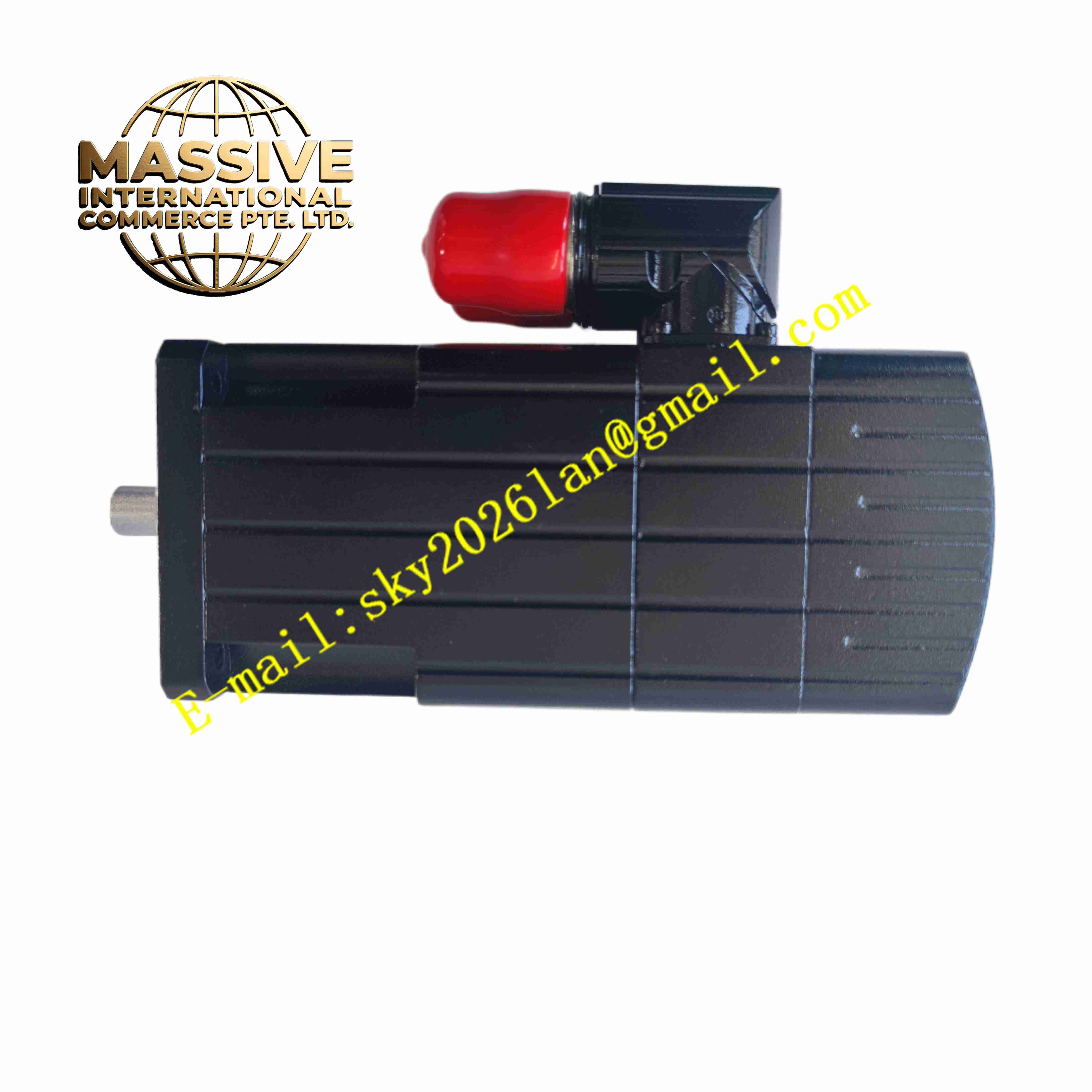
Description
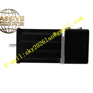
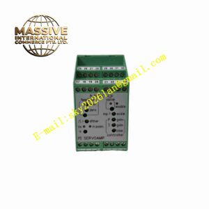
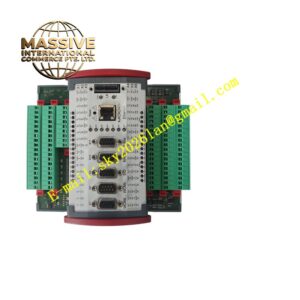
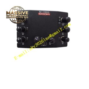
Moog G403-552A
Technical Specifications:
- Power Supply: ±15 VDC or 24 VDC optional
- Input Signal: ±10 V analog command and feedback signal
- Output: Regulated current output for servo valve torque motor
- Control Modes: Position loop, pressure loop, force loop configurable
- Bandwidth: High dynamic response for fast hydraulic servo systems
- Operating Temperature: -20 °C to +65 °C
- Storage Temperature: -40 °C to +85 °C
- Mounting: DIN rail or panel mount
- Relative Humidity: 5% to 90%, non-condensing
Function Features:
- High precision analog closed-loop control for hydraulic servo valves
- Support position, pressure or force control loop configuration
- Adjustable proportional gain, integral gain and derivative gain
- Built-in signal conditioning for LVDT, RVDT and pressure transducer feedback
- Output current limit protection to prevent servo valve overload
- Fault monitoring for signal loss and overcurrent
- Zero offset and span adjustment potentiometers
- Enable/disable control input for safety interlock
Application Scenarios:
- Material fatigue test hydraulic servo systems
- Automotive component durability test benches
- Aerospace hydraulic simulation test rigs
- Steel mill continuous casting hydraulic control
- High precision hydraulic press closed-loop control
Material Composition:
- Housing: Aluminum alloy metal enclosure
- Main PCB: Multilayer FR4 fiberglass printed circuit board
- Core Components: Precision operational amplifiers, current output power stage
- Terminals: Screw copper terminal blocks for signal, power and valve wiring
- Passive Components: Low drift precision resistors and capacitors
- Adjustment Components: Multi-turn trimming potentiometers
Structural Features:
- Compact metal shielded housing for electromagnetic noise suppression
- Terminal blocks arranged on one side for field wiring
- Top cover removable for access to gain and offset potentiometers
- Internal separated analog signal zone and power output zone
- Mounting holes for panel installation or DIN rail adapter mounting
Working Principle: Setpoint command signal and sensor feedback signal enter the controller. The analog circuit computes error between target value and measured feedback. PID control circuit processes error signal and generates corresponding drive current for servo valve torque motor. The current adjusts servo valve spool position to regulate hydraulic flow and pressure. Current limit circuit restricts maximum output current to protect servo valve. The module monitors input signal integrity and triggers fault state when signal loss occurs.
Installation Requirements:
- Install module inside dry control cabinet away from hydraulic oil mist
- Use shielded twisted pair cables for command, feedback and valve wiring
- Separate low-level analog signal cables from high power cables
- Supply stable regulated DC power and connect protective earth
- Maintain ventilation space around module for heat dissipation
- Avoid strong electromagnetic field near installation location
Usage Notes:
- Tune PID gain parameters according to hydraulic mechanical load during commissioning
- Calibrate zero offset and span after wiring completion
- Set current limit to match servo valve rated coil current
- Use external safety enable interlock for emergency stop
- Disconnect power before adjusting internal potentiometers
- Check cable shielding and grounding to reduce noise interference