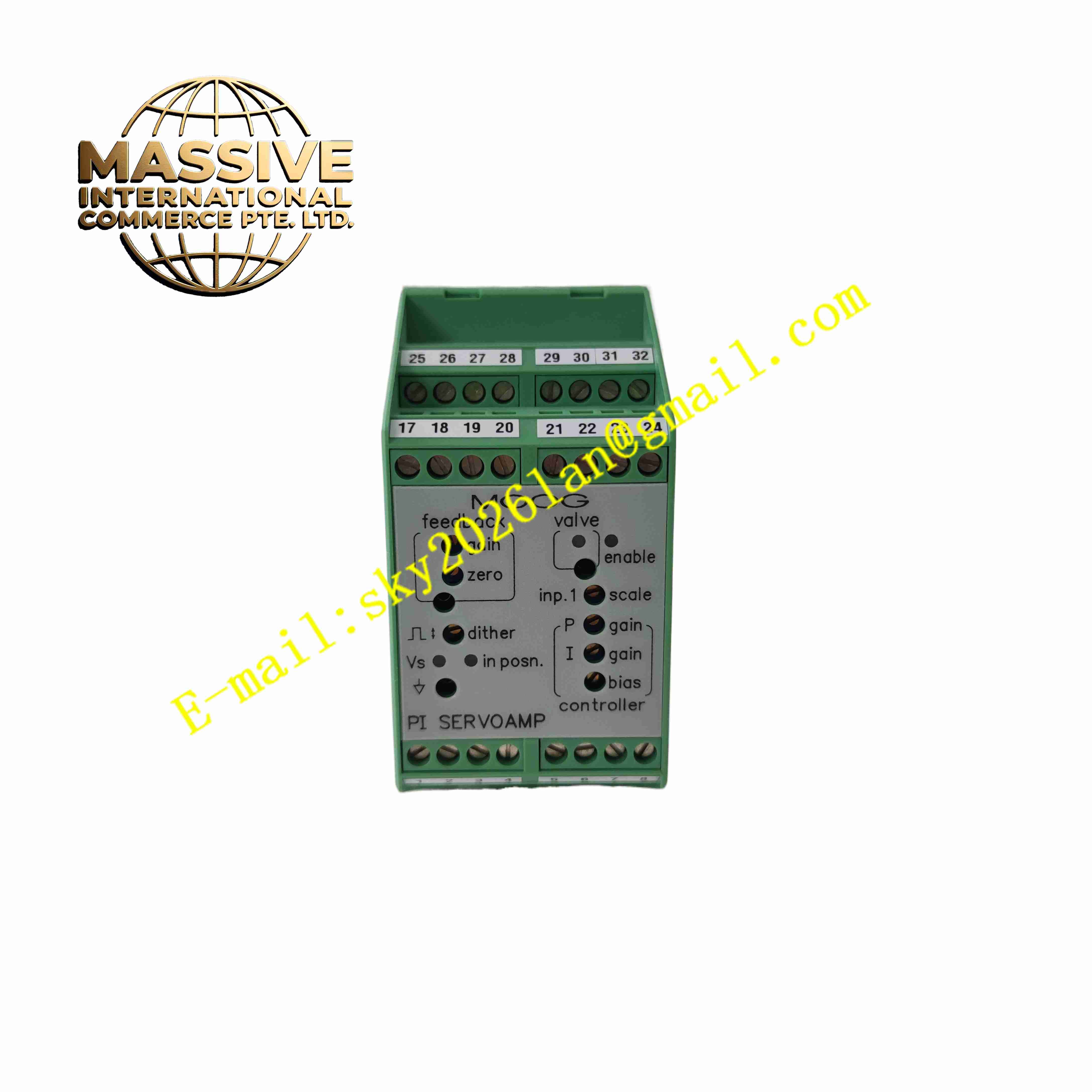
Description
MOOG G122-829A-001 P-I Servo Amplifier
Technical Specifications
- Brand: MOOG
- Model: G122-829A-001
- Product Type: P-I servo amplifier / servo valve controller
- Control Mode: Proportional, integral, or combined P-I control
- Input Signals: Command input, enable input, and feedback input
- Command Input: ±10 V analog or 4-20 mA, selectable
- Feedback Input: ±10 V or 4-20 mA, differential or single-ended depending on configuration
- Output Type: Voltage or current output
- Voltage Output: ±10 V, minimum load typically 200 Ω
- Current Output: ±5 mA to ±100 mA range, selectable
- 4-20 mA Output Load: Maximum load typically 500 Ω
- Power Supply: +24 VDC, typically 18 VDC to 30 VDC
- Dither Function: Built-in dither signal generator, selectable on/off
- Status Indicators: Front-panel LEDs for power, enable, and fault indication
- Test Points: Front-panel test points for setup and troubleshooting
- Mounting: DIN-rail mounted compact module
- Operating Temperature: 0°C to +50°C typical for control cabinet installation
- EMC Compliance: Designed to meet CE-related emission and immunity requirements with proper wiring
Functional Features
- Configurable P-I Control: Internal switches allow selection of proportional, integral, or combined control modes.
- Multiple Input Types: Accepts single-ended and differential analog inputs for flexible system integration.
- Selectable Input Range: Supports ±10 V or 4-20 mA command and feedback signals.
- Adjustable Gain and Offset: Front-panel potentiometers allow gain, zero, and tuning adjustments.
- Valve Drive Output: Provides voltage or current output suitable for two-coil servo valves.
- Dither Signal: Reduces valve stiction and improves low-speed motion stability.
- Enable Input: Allows external safety or machine-control interlocks.
- Diagnostic Test Points: Support fast commissioning and maintenance.
- Compact DIN-Rail Design: Saves space inside industrial control cabinets.
- Robust Analog Architecture: Reduces complexity compared with networked digital controllers in simple closed-loop applications.
Application Scenarios
- Electrohydraulic servo valve control
- Industrial hydraulic position, speed, pressure, and force control
- Injection molding machines
- Die casting machines
- Test rigs and material testing equipment
- Robotics and motion simulation systems
- Presses and forming machines
- Process automation requiring precise hydraulic actuation
Performance Parameters
- Control Accuracy: High closed-loop accuracy when properly tuned with valve and feedback sensor.
- Response Stability: Stable proportional and integral response for hydraulic actuator control.
- Signal Conditioning: Sums command and feedback signals to generate an error signal for amplification.
- Output Flexibility: Supports voltage, current, and 4-20 mA output configurations.
- Dither Performance: Improves valve resolution and reduces stick-slip behavior.
- Diagnostic Accessibility: Front-panel LEDs and test points simplify troubleshooting.
Material Composition
- Housing: Industrial-grade plastic or metal-reinforced enclosure for DIN-rail mounting.
- PCB: Analog control board with proportional and integral amplifier circuits.
- Power Circuit: 24 VDC input regulation and protection components.
- Output Stage: Power driver stage for valve coil or actuator interface.
- Terminal Block: Screw terminals for signal, power, and output connections.
- Adjustment Components: Potentiometers and internal DIP switches for configuration.
- Status LEDs: Indicate power, enable, output, and fault conditions.
Structural Features
- DIN-Rail Mounting Clip: Allows fast installation and removal from control panels.
- Front-Panel Controls: Potentiometers and test points are accessible without opening the housing.
- Screw Terminal Connections: Support reliable wiring for industrial environments.
- Ventilation Openings: Provide airflow for internal electronic cooling.
- Compact Module Width: Fits into standard industrial control cabinet layouts.
- Shielded Internal Layout: Helps reduce electromagnetic interference effects.
Working Principle
The G122-829A-001 receives a command signal representing the desired valve position, speed, pressure, or force. It also receives a feedback signal from a sensor such as an LVDT, pressure transducer, or position transducer. The amplifier compares the command and feedback signals, generates an error signal, and applies proportional and/or integral amplification. The processed signal drives the servo valve coil or output stage, adjusting hydraulic flow or pressure until the feedback matches the command. The dither function superimposes a small high-frequency signal to reduce mechanical friction effects in the valve.
Installation Requirements
- Install on a horizontal DIN rail inside a ventilated industrial control cabinet.
- Maintain adequate clearance above and below the module for cooling airflow.
- Use a clean and stable +24 VDC power supply.
- Route signal cables separately from power cables and motor drives.
- Use shielded cables for analog command and feedback signals.
- Connect cable shields to chassis ground at the cabinet entry point.
- Verify input type, output type, and control mode before commissioning.
- Confirm valve coil compatibility and output current range.
Precautions for Use
- Do not exceed the rated supply voltage or output current.
- Do not adjust internal switches without understanding the control loop.
- Verify signal polarity before enabling the amplifier.
- Do not operate with loose terminals or damaged wiring.
- Keep the module away from strong electromagnetic interference sources.
- Use proper hydraulic filtration when controlling servo valves.
- Replace failed amplifiers with the same model and configuration.
- Only qualified control or hydraulic engineers should commission the device.
- Refer to the official MOOG documentation for exact wiring, switch settings, and safety instructions.