Description
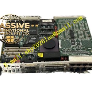
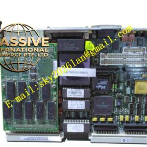
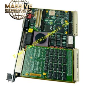
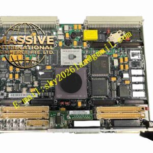
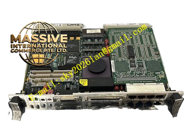
Motorola MVME 374-1
Technical Specifications:
- Brand: Motorola
- Model: MVME 374-1
- Product Type: CPU Parallel I/O Module
- System Compatibility: PLC/DCS System Module
Functional Features:
- High Integration: Consolidates the CPU and parallel I/O onto a single board, reducing system latency and wiring complexity.
- High-Speed Data Processing: Optimized specifically for parallel data transmission to enhance overall system throughput.
- Quality Assurance: Backed by reliable warranty and technical support.
Application Scenarios:
Applicable to large-scale industrial machinery control, Automated Test Equipment (ATE), laboratory test stands, and traditional industrial control networks requiring high-reliability Real-Time Operating Systems (RTOS).
Performance Parameters:
- Control Precision: Extremely high, ensuring equipment speed or load is strictly maintained within set thresholds.
- Environmental Adaptability: Exhibits outstanding resistance to vibration and shock.
- Operating Voltage: Wide-range DC/AC input adapting to different power supply environments.
Material Composition:
The housing is constructed from high-strength flame-retardant engineering plastics or die-cast metal. Internal circuit boards are coated with three-proof paint, and pins are gold-plated using high-conductivity alloys.
Structural Characteristics:
Adopts a standard industrial modular package equipped with high-reliability industrial-grade connectors. Features clear terminal markings and status indicator interfaces.
Working Principle:
Real-time acquisition of sensor feedback signals, followed by PID calculation and logic judgment via an internal microprocessor, outputs precise control current or voltage signals to drive actuators, forming a closed-loop control system.
Installation Requirements:
Must be installed in a well-ventilated electrical control cabinet, away from extreme heat sources. Wiring must strictly follow the schematic diagram, and shielding layers must be reliably grounded at a single end.
Usage Precautions:
Always cut off the system power before operation; inserting or removing connectors while energized is strictly prohibited. Installation and debugging must be performed by qualified professional engineers in strict compliance with Electrostatic Discharge (ESD) protocols.