Description
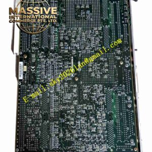
Motorola MVME162-243
Technical Specifications
- Microprocessor: 32 MHz MC68040 with 8KB cache, MMU, and FPU.
- Memory: 4MB DRAM and 512KB battery-backed SRAM.
- Network & Storage: Integrated 10Base-T Ethernet and SCSI-1 bus controller, both supporting 32-bit local bus DMA.
- Non-Volatile Storage: 8KB NVRAM with a real-time clock (RTC).
Functional Features
- Full support for VMEbus D64 specifications for maximum throughput.
- Dual serial ports for legacy peripheral connectivity.
- Comprehensive onboard diagnostics via the 162Bug monitor.
- Seven-level VMEbus interrupt handling for prioritized task management.
Application Scenarios
Ideal for SCADA servers, test and measurement platforms, military/aerospace ground support equipment, and data logging systems.
Performance Parameters
- Interrupt System: Four-level requestor, seven-level interrupter and handler.
- Cooling Requirement: Forced air cooling required for 0°C to +55°C ambient operation.
- Relative Humidity: 5% to 95% non-condensing.
Material Composition
Industrial-grade PCB with gold-plated VME edge connectors and high-quality tantalum capacitors.
Structural Characteristics
6U double-high VME module featuring front panel debug serial ports, status LEDs, and standard P1/P2 backplane connectors.
Working Principle
The processor executes real-time control tasks while utilizing dedicated DMA channels to rapidly transfer network packets and disk I/O directly to memory, significantly reducing CPU overhead.
Installation Requirements
- Verify backplane pin definitions support the specific Ethernet and SCSI configurations.
- Use shielded twisted-pair cables for Ethernet and properly terminated SCSI ribbon cables.
- Check front panel LEDs to confirm successful boot sequence.
Usage Precautions
- Avoid routing serial communication lines parallel to high-voltage power cables.
- Ensure robust chassis grounding to prevent common-mode interference.
- Charge NVRAM and RTC batteries before long-term storage to prevent data loss.