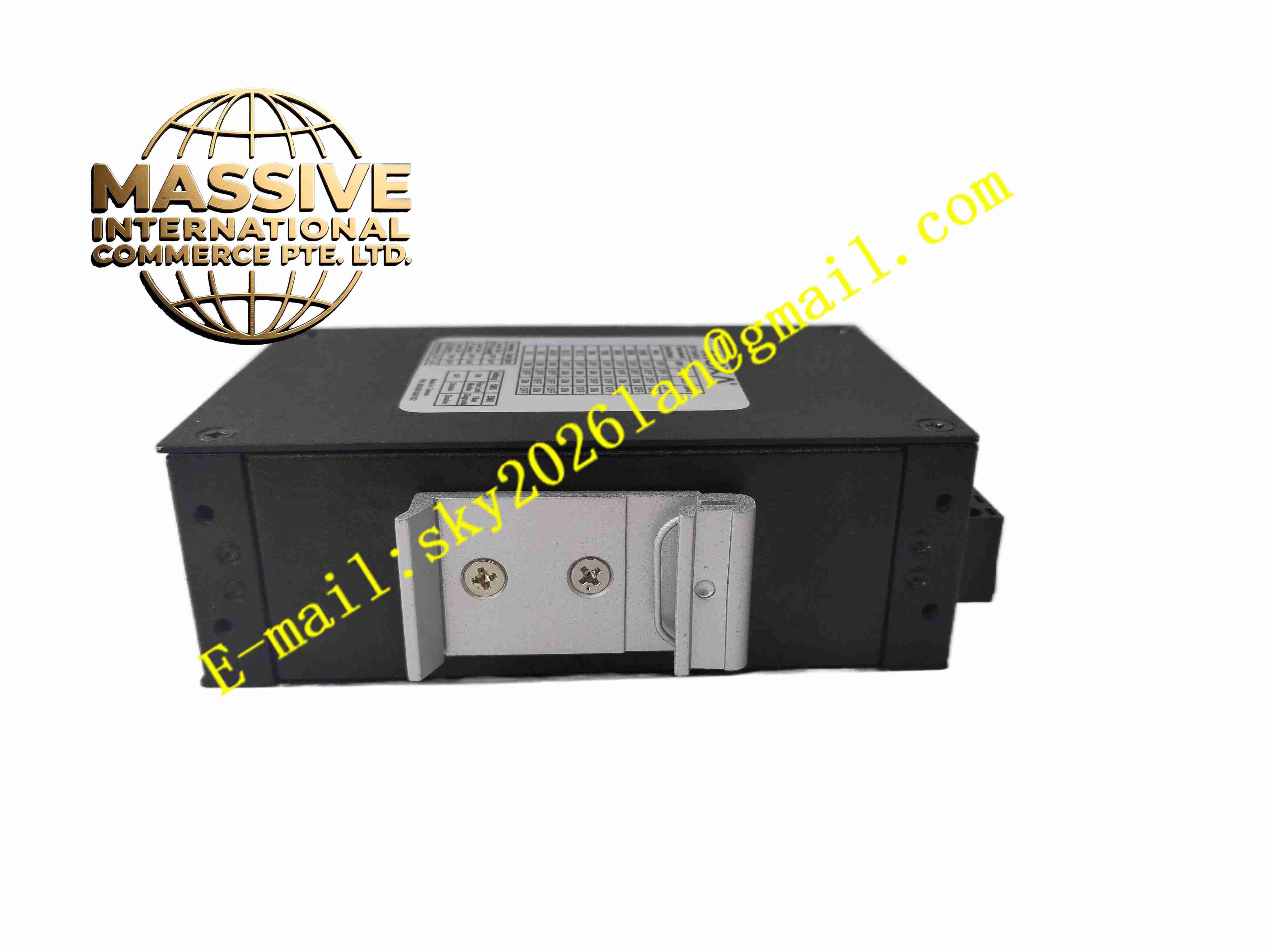
Description
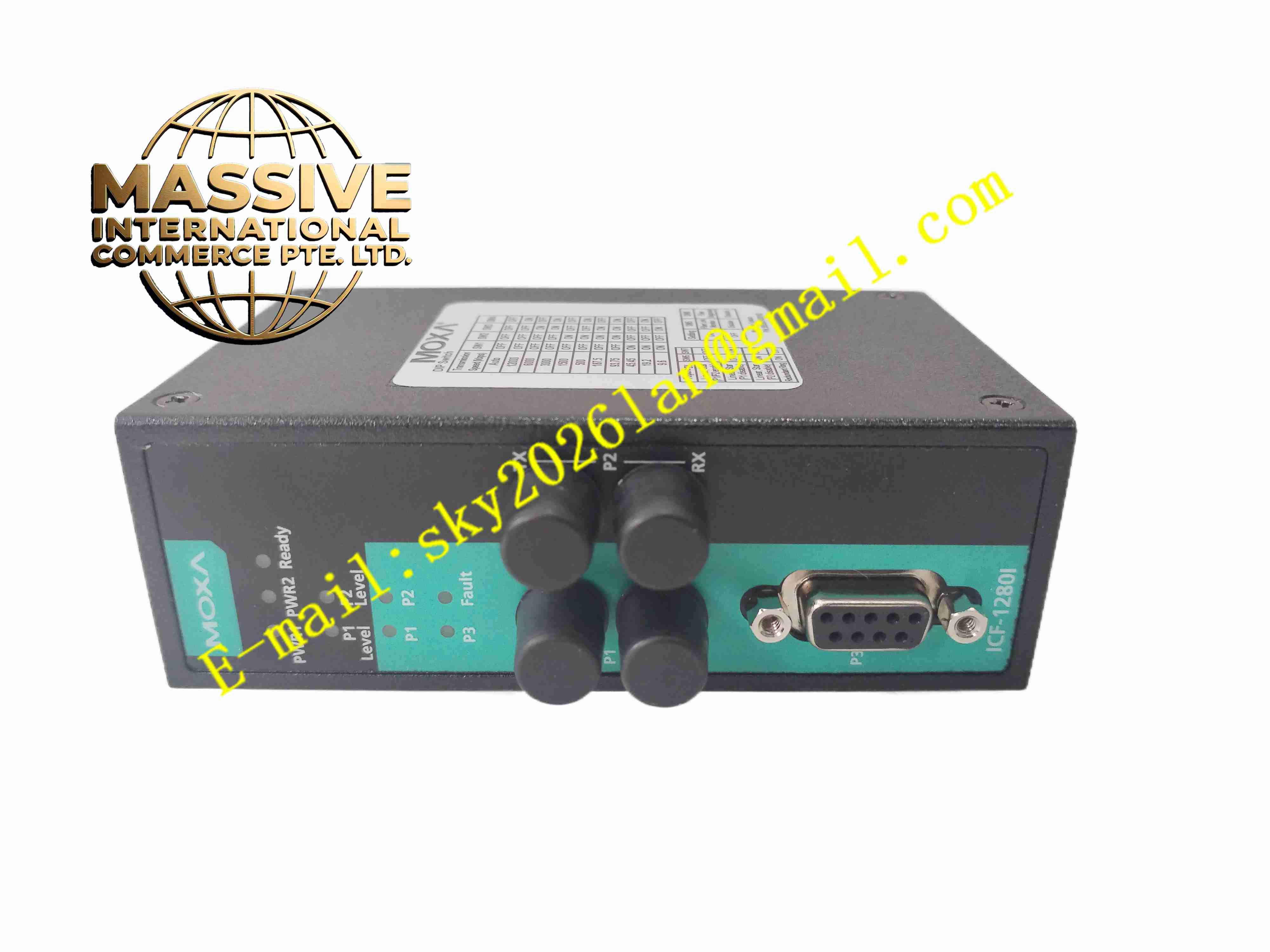
MOXA ICF-1280I-M-ST-T
Technical Specifications:
- Fieldbus Interface: PROFIBUS DP, DB9 female connector
- Fiber Interface: Multi-mode 100BaseFX, ST connector
- PROFIBUS Baud Rate: 9600 bps up to 12 Mbps, auto baud rate detection
- Optical Wavelength: 820 nm
- Optical Transmit Power: -14 dBm
- Optical Receiver Sensitivity: -28 dBm
- Optical Link Budget: 14 dB
- Maximum Transmission Distance: 4 km for multi-mode fiber
- Electrical Isolation: 2 kV isolation between PROFIBUS side and internal circuit
- Power Supply: 12 VDC to 48 VDC, dual redundant power inputs
- Rated Current: 370 mA @ 12 VDC
- Power Protection: Overcurrent protection
- Operating Temperature: -40 °C to +75 °C
- Storage Temperature: -40 °C to +85 °C
- Relative Humidity: 5% to 95%, non-condensing
- Protection Class: IP30
- Dimensions: 39 mm × 115 mm × 70 mm
- Weight: 225 g
- Mounting: DIN rail mounting
- Certifications: CE, FCC, ATEX, IEC EMC compliance
Function Features:
- Redundant fiber ring network function with zero recovery time upon fiber breakage
- Built-in fiber signal strength diagnosis to monitor optical power in real time
- PROFIBUS bus fault protection mechanism to prevent data corruption during bus disturbance
- Relay alarm output triggered by fiber link failure or power loss
- Dual redundant DC power inputs to eliminate single point power failure
- 2 kV galvanic isolation blocks surge and common-mode noise from field bus
- Auto baud rate adaptation for PROFIBUS DP network without manual baud setting
- LED status indicators for power, fiber link, PROFIBUS activity and fault status
- Compact metal housing for rugged industrial cabinet deployment
- Support point-to-point and ring topology PROFIBUS fiber networking
Application Scenarios:
- Factory automation PROFIBUS DP long-distance bus extension
- Automotive assembly line PROFIBUS ring network construction
- Metallurgy plant fieldbus anti-interference transmission
- Water treatment plant distributed PROFIBUS control network
- Oil and gas processing plant fieldbus isolation and distance extension
- Power plant PROFIBUS DP remote I/O communication
Material Composition:
- Enclosure: Painted aluminum alloy metal housing
- Main PCB: FR4 multilayer fiberglass printed circuit board
- Optical Components: Multi-mode optical transceiver module, ST fiber receptacle
- PROFIBUS Connector: DB9 female metal shell connector
- Power Terminals: Tin-plated copper screw terminal blocks
- Relay: Industrial signal relay for fault alarm output
- Passive Components: Surge suppression diodes, high temperature resistors and capacitors
Structural Features:
- Slim rectangular DIN rail snap-on metal enclosure
- Front panel equipped with multi-color LED indicators and ST fiber ports
- DB9 PROFIBUS port arranged on front panel for fieldbus wiring
- Screw terminal blocks on front for dual DC power supply connection
- Internal PCB layout separates optical circuit, PROFIBUS signal circuit and power circuit
- Rear integrated DIN rail clip for fast installation and removal
- Internal metal shielding structure reduces electromagnetic interference
Working Principle: PROFIBUS DP electrical differential signals enter the unit via DB9 connector. The internal circuit converts electrical differential signals into optical signals and transmits through multi-mode fiber. At the receiving end, optical signals convert back to PROFIBUS differential electrical signals for PROFIBUS bus communication. When configured in ring topology, the device monitors bidirectional fiber links continuously. If one fiber path breaks, the network switches data transmission to backup fiber path instantly without data interruption. The optical power detection circuit measures received optical power continuously and triggers relay alarm when optical power drops below threshold value. Dual power circuit monitors both power inputs and keeps device running when one power supply fails.
Installation Requirements:
- Mount the converter on standard 35 mm DIN rail inside industrial control cabinet
- Use shielded twisted pair PROFIBUS cable for DB9 bus wiring
- Match multi-mode ST fiber patch cord with device optical port
- Connect two independent DC power sources to dual power terminals for redundant power configuration
- Separate PROFIBUS signal cables and fiber cables from high-current power cables
- Verify cabinet ambient temperature stays within -40 °C to +75 °C
- Maintain proper cabinet ventilation to avoid heat accumulation
- Set PROFIBUS terminal resistor at the two physical endpoints of PROFIBUS electrical bus
Usage Notes:
- Check fiber connector cleanliness before insertion, clean ST fiber end face if contaminated
- Verify PROFIBUS baud rate consistency across all nodes on the bus
- Configure relay alarm contact wiring according to remote monitoring requirement
- Disconnect DC power supply before replacing fiber module or opening housing
- Inspect fiber link status and optical power reading during routine maintenance
- Avoid bending optical fiber cable beyond minimum bend radius
- Backup network topology plan before modifying PROFIBUS fiber ring