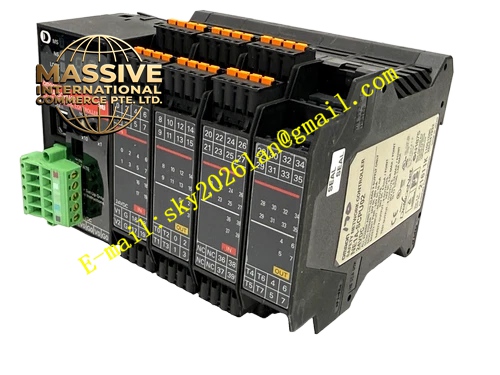
Description
OMRON H3CR‑A8E
Technical Specifications: Rated supply voltage AC100‑240V 50/60Hz, DC100‑125V; allowable voltage fluctuation range 85‑110% of rated value; power consumption approximately 2VA (0.9W); total 18 selectable time ranges covering 0.05 s up to 300 h; supported operating modes: ON‑delay, flicker ON‑start, flicker OFF‑start, interval, one‑shot output; output contacts: 1‑circuit timed‑action SPDT contact, 1‑circuit instantaneous‑action SPDT contact; rated contact capacity resistive load AC250V 5A, DC30V 5A; mechanical service life ≥20 000 000 operations; electrical service life ≥100 000 operations under rated resistive‑load conditions; operating temperature ‑10‑55°C; storage temperature ‑25‑65°C; operating humidity 35‑85%RH without condensation; plug‑in 8‑pin socket connection; weight approximately 90g; front‑panel IP40 protection gradeオムロン.
Functional Features: Multiple configurable timing operation modes satisfy diverse industrial timing‑logic requirements; wide‑span selectable time ranges from short‑second intervals up to long‑hour durations; simultaneous provision of timed‑action and instantaneous‑action relay contacts; front‑panel rotary knobs for direct time‑value and mode‑selection adjustment; dual LED indicators show power‑supply status and timing‑output status; plug‑in socket‑mounting structure enables fast replacement without re‑wiring.
Application Scenarios: Time‑delay control inside industrial control cabinets; sequential start‑up control for automation equipment; timing interlock circuits for packaging machinery; timing trigger of alarm‑signal loops; spare‑part replacement for legacy timer‑relay automation installations.
Performance Parameters: Timing accuracy deviation ≤±0.2% of full‑scale range; recovery time ≤0.1 s; withstands ±1.5 kV square‑wave noise interference on power terminals; impulse‑voltage withstand capability reaches 5 kV; complies with IEC industrial control‑component standards; stable continuous operation within cabinet‑mount environments.
Material Composition: Front‑panel housing constructed from off‑white flame‑retardant engineering plastic; internal FR‑4 printed‑circuit board with timing oscillation chip; electromagnetic relay assemblies with silver‑alloy contact points; tin‑plated plug‑in pin terminals; high‑brightness LED status indicators; rotary mechanical adjustment knobs.
Structural Features: Standard 48 × 48 mm square 1/16‑DIN panel‑mount form factor; front‑panel rotary adjustment knobs for time‑range and mode selection; dual LED indicator windows on front face; bottom‑side 8‑pin plug‑in pin array; compatible with standard 8‑pin timer sockets for DIN‑rail or panel‑base mounting.
Working Principle: When rated supply voltage applies to timer power terminals, internal oscillation circuit generates stable reference clock signal. Internal counting circuit accumulates clock pulses according to preset time setting value. Upon completion of preset timing duration, drive circuit triggers timed‑action relay contact switching. Instantaneous‑action relay contact executes switching synchronously with power‑supply activation independent of timing progress. After power‑supply cut‑off, internal reset circuit returns all relay contacts back to original static state.
Installation Requirements: Install matched 8‑pin timer socket either on DIN rail or control‑panel mounting surface; insert H3CR‑A8E timer fully into socket ensuring complete pin engagement; separate timer‑socket wiring for power‑supply loop and load‑output loop; reserve adequate ventilation clearance around timer body inside control cabinet.
Usage Notes: Never exceed rated contact voltage and current limits; install surge‑absorbing components when driving inductive‑type loads; confirm coil supply voltage matches control‑system power‑supply specification; avoid continuous high‑temperature operating environments; perform periodic inspection for contact abrasion under high‑frequency switching‑cycle operating conditions.