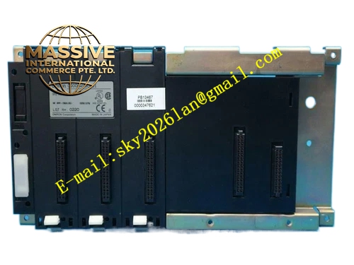
Description
OMRON C200HW-BC031
Technical Specifications:
- Brand: OMRON
- Model: C200HW-BC031
- Product Type: CPU Backplane (Base Unit)
- Compatible System: C200HW Series PLC
- Number of Slots: 3 slots
- Slot Type: CPU slot + I/O module slots
- Mounting: DIN rail or panel mount
- Bus Type: C200HW series backplane bus
Functional Features:
- 3-slot configuration for CPU, power supply, and I/O modules
- Provides electrical bus connections between all mounted modules
- Supports C200HW series CPU and I/O units
- Compact design for space-efficient installations
- DIN rail mounting for easy panel installation
Application Scenarios:
- Small to medium-scale PLC control systems
- Machine automation applications
- Process control systems
- Building automation
- Any application using C200HW series PLC modules
Performance Parameters:
- Number of Slots: 3
- Compatible Modules: series
- Bus Communication: High-speed backplane bus
Material Composition:
- Industrial-grade printed circuit board
- Metal DIN rail mounting bracket
- Plastic housing
- Backplane connector slots
Structural Features: The -BC031 features a compact 3-slot design with standardized connector slots for mounting series modules. It includes a DIN rail mounting bracket for easy installation in control panels and provides the electrical pathways (bus) for communication between the CPU, power supply, and I/O modules.
Working Principle: The -BC031 serves as the physical and electrical backbone of the PLC system. It provides mechanical mounting for modules and electrical bus connections that allow the CPU to communicate with all installed I/O and special function modules. Power from the power supply unit is distributed through the backplane to all connected modules.
Installation Requirements:
- Mount on DIN rail or panel using mounting holes
- Install modules by sliding them onto the backplane connectors
- Ensure modules are securely locked in place
- Provide adequate ventilation around the backplane
- Ensure proper grounding
Usage Notes:
- Do not exceed the maximum number of modules for the slot configuration
- Ensure all modules are compatible with the series
- Check module seating and locking mechanisms during maintenance
- Do not install or remove modules while power is on
- Store in dry conditions