Description
OMRON NE2A‑SCPU01
Technical Specifications: Safety program capacity 8K steps; maximum expandable safety I/O points 1024 points; built‑in local safety input 16 points, built‑in local safety output 8 points; working supply voltage DC20.4‑28.8V; typical operating current 450mA; built‑in DeviceNet Safety communication interface; backplane bus power‑supply for expansion modules; operating temperature 0‑55°C; storage temperature ‑20‑75°C; operating humidity 10‑90%RH without condensation; lithium backup battery for safety‑retentive data storage; multi‑group LED indicators for RUN status, fault alarm and channel status; DIN‑rail rack‑slot installation; weight 460g; CE, UL, cULus, TÜV safety approvals.
Functional Features: Supports safety‑ladder logic programming for machine‑safety applications; built‑in DeviceNet Safety interface for safety‑network connection; hardware self‑diagnosis identifies safety‑program errors, backplane‑bus faults and internal hardware failures; backup lithium battery preserves retentive safety memory data during main‑power loss; fault‑code storage mechanism facilitates on‑site troubleshooting; full compatibility with complete range of NE2A‑series safety I/O and communication expansion modules.
Application Scenarios: Safety control for automated assembly machinery; robot peripheral safety interlock systems; packaging‑machine safety monitoring; production‑line emergency‑stop and safety‑door control; spare‑part replacement for legacy NE2A‑series safety automation installations.
Performance Parameters: Safety‑logic scan cycle meets SIL3 safety‑control timing requirements; electromagnetic‑compatibility performance satisfies industrial cabinet‑mount equipment standards; vibration‑resistance and shock‑resistance comply with IEC60068 test specifications; supports continuous 24‑hour operation inside industrial control cabinets; dual‑channel safety signal evaluation mechanism guarantees safety‑circuit reliability.
Material Composition: Housing made from black V0 flame‑retardant engineering plastic; internal FR‑4 multilayer glass‑fiber printed‑circuit board; gold‑plated backplane edge‑connector contacts; lithium backup‑battery assembly; industrial safety‑grade main‑control processing chip; high‑brightness multi‑color LED status indicators.
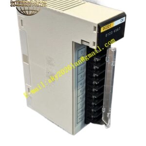
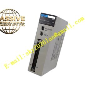
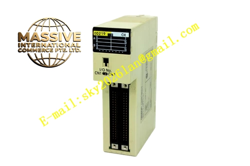
Structural Features: NE2A‑series rack‑slot mechanical profile; gold‑plated edge‑connector on rear housing surface interfaces with NE2A rack backplane bus; front‑panel DeviceNet Safety communication port; multiple groups of status LED indicators arranged on front face; locking latches on both sides fasten CPU unit securely into designated rack CPU slot.
Working Principle: NE2A‑SCPU01 runs cyclic safety‑logic scan cycles: reads all safety‑input signal states from backplane bus and built‑in local channels; executes user‑compiled safety‑ladder logic sequentially; refreshes safety‑output state data and distributes data onto backplane bus. DeviceNet Safety communication port handles safety‑program upload‑download and safety‑network data exchange. Internal self‑diagnosis circuit continuously monitors hardware operating conditions, illuminates alarm indicators and stores fault‑code information when abnormal events occur. Backup lithium battery maintains safety‑retentive memory content upon main‑supply power failure.
Installation Requirements: Install ‑SCPU01 into designated CPU slot of main rack; fasten complete rack onto cabinet DIN rail; reserve adequate heat‑dissipation clearance surrounding module housing; deploy shielded cable for DeviceNet Safety communication wiring; physically separate safety‑signal cables from high‑power dynamic cables; implement reliable protective grounding for control cabinet.
Usage Notes: Hot‑swap operation for this CPU unit is strictly prohibited; replace backup lithium battery according to specified service cycle to prevent loss of safety‑retentive data; complete full safety‑program backup after programming completion; read CPU stored fault‑codes for failure‑analysis work; deployment in environments with corrosive gas or condensation is forbidden.