Description
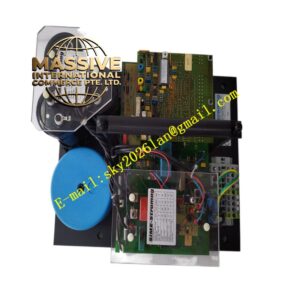
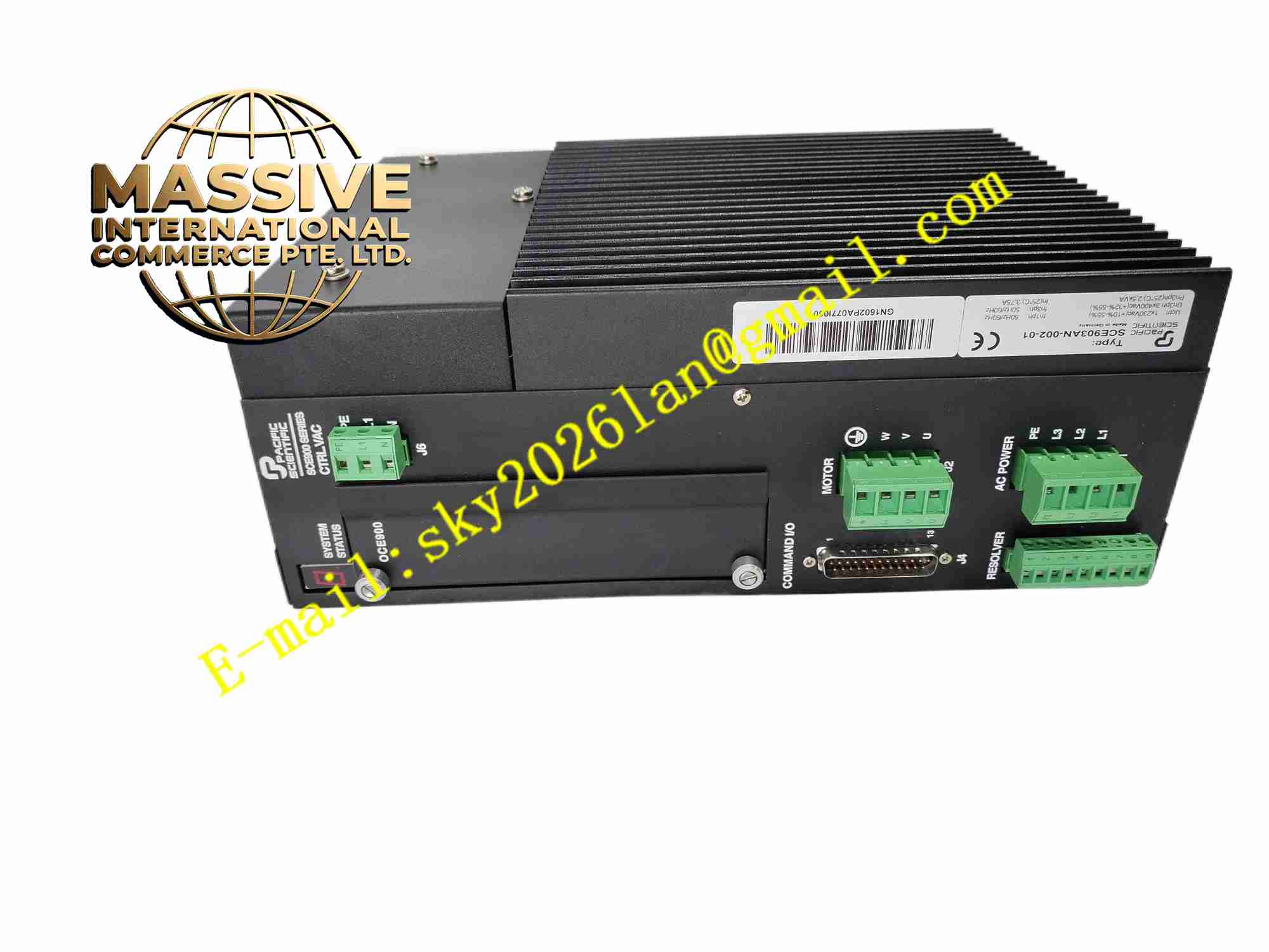
PACIFIC SCIENTIFIC SCE903AN-002-01
Technical Specifications Brand: Pacific Scientific Model: SCE903AN-002-01 Input Power: 120/240 VAC single phase, 50/60 Hz Continuous Output Current: 9 A RMS Feedback: Incremental encoder, resolver, hall effect sensor Control Modes: Torque, velocity, position Command Interface: ±10 V analog, pulse/direction digital command Digital I/O: Multiple opto-isolated programmable discrete I/O Operating Temperature: 0°C to +50°C Protection Grade: IP20 cabinet mount Mounting: Panel or DIN rail installation
Functional Features Supports three standard closed-loop motion control modes. Multiple feedback input options adapt to different servo motor types with encoder or resolver. Accept analog ±10V command or pulse-direction position command from external controller. Built-in motion profile generator for simple positioning tasks without external controller. Programmable digital I/O connect to limit switches, home sensors and machine interlock relays. Comprehensive fault diagnostics with LED alarm indication for overcurrent, overvoltage and encoder failure. PC software support for advanced parameter tuning, auto-tuning and fault log reading.
Application Scenarios Automated assembly machinery, printing machine motion axes, material cutting equipment, packaging production lines, robotic auxiliary axes, automated test fixture motion control.
Performance Parameters High bandwidth current loop delivers fast dynamic torque response. Auto-tuning function optimizes servo loop gain to suppress mechanical resonance. Rapid fault detection response for wiring and hardware anomalies. Stable speed regulation under variable mechanical load. High repeatability for repetitive positioning cycles.
Material Composition Enclosure: Aluminum alloy extruded heat sink housing. PCB: FR4 multilayer power board and control board with conformal coating. Core Components: IGBT power module, DSP motion controller, resolver signal conditioner, opto-isolation chips. Terminals: Screw type high-current power terminals and signal terminal blocks. Indicators: SMD LED array for status and fault display.
Structural Features Vertical compact housing, rear side with aluminum heat sink. Front panel arranges status LEDs and terminal access area. Internal PCB layout physically isolates high-power power circuit and sensitive feedback signal circuit. External mounting holes on housing for fixed panel installation. Optional DIN rail adapter for cabinet rail mounting.
Working Principle AC power input passes EMC filter and rectifier to produce DC bus voltage. DSP processor receives motion command from analog port or pulse direction input. Processor generates PWM signals to drive IGBT power stage and supply three-phase current to servo motor. Encoder or resolver feeds rotor position and speed back to processor to close control loop. Onboard monitoring circuit continuously monitors electrical and thermal conditions and triggers protection shutdown at fault threshold.
Installation Requirements Install drive vertically inside ventilated control cabinet. Deploy shielded motor cable and feedback cable, terminate shield at drive side. Physically separate power cables and signal cables to reduce noise interference. Complete wiring inspection, set motor parameters and run servo auto-tuning before commissioning. Maintain free air flow through heat sink surface.
Usage Notes High voltage remains on DC bus capacitors after power off, wait for capacitor discharge before maintenance. Match motor rated voltage and feedback type with drive configuration. Check resolver or encoder wiring carefully to avoid feedback error. Periodically clean dust deposits on heat sink. Save parameter file before modifying configuration.