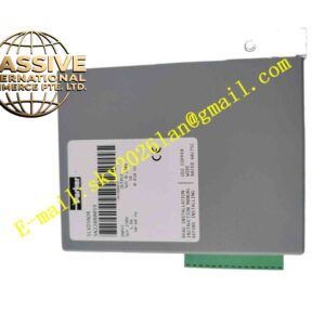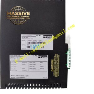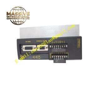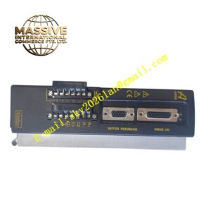
Description
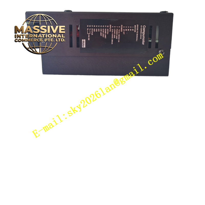
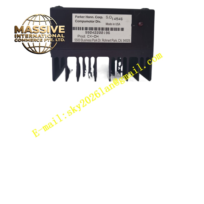
Parker CX-DH
Technical Specifications Module power supplied by Compax3 drive internal bus; supports dedicated high-speed digital motion bus; cyclic real-time process data exchange for position, velocity and torque commands; digital isolation between fieldbus side and drive power stage; compatible with multiple Compax3 hardware variants; operating temperature 0 ℃ to +55 ℃; plug-in side slot installation on Compax3 drive.
Functional Features High priority cyclic motion data transfer for synchronised multi-axis systems; hardware timestamp of received setpoint frames; drive fault and warning status transmission to master controller; configurable PDO mapping for process data; bus error detection and loss-of-master safety reaction.
Application Scenarios Packaging multi-axis synchronisation, printing register control, laser cutting positioning axes, automated assembly transfer lines, material forming machine servo axes.
Material Composition FR4 signal PCB; isolated bus transceiver chips; gold-plated edge connector for Compax3 internal slot; plastic module housing; surface-mount EMC filtering components.
Structural Characteristics Small plug-in daughter card form; edge connector inserts into dedicated expansion slot on Compax3 servo drive; external fieldbus connector located on module edge; digital ground isolation barrier separates drive power electronics and bus communication circuits.
Working Principle The module receives cyclic motion command frames from the master controller over the fieldbus. It translates bus protocol data into internal Compax3 drive setpoint values and forwards encoder position and status data back to the master. Bus communication errors trigger configurable drive safe state functions.
Installation Requirements Power off Compax3 drive before inserting CX-DH module; lock module retention clip after insertion; use specified shielded bus cable and follow bus topology rules; verify firmware compatibility between drive and CX-DH module.
Operation Notes Save axis parameter file before module replacement; configure master controller node mapping after hardware swap; inspect bus cable shielding in high-frequency inverter environments.