Description
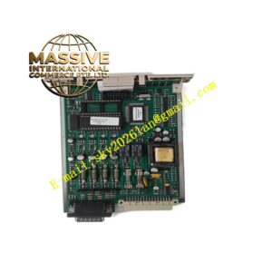
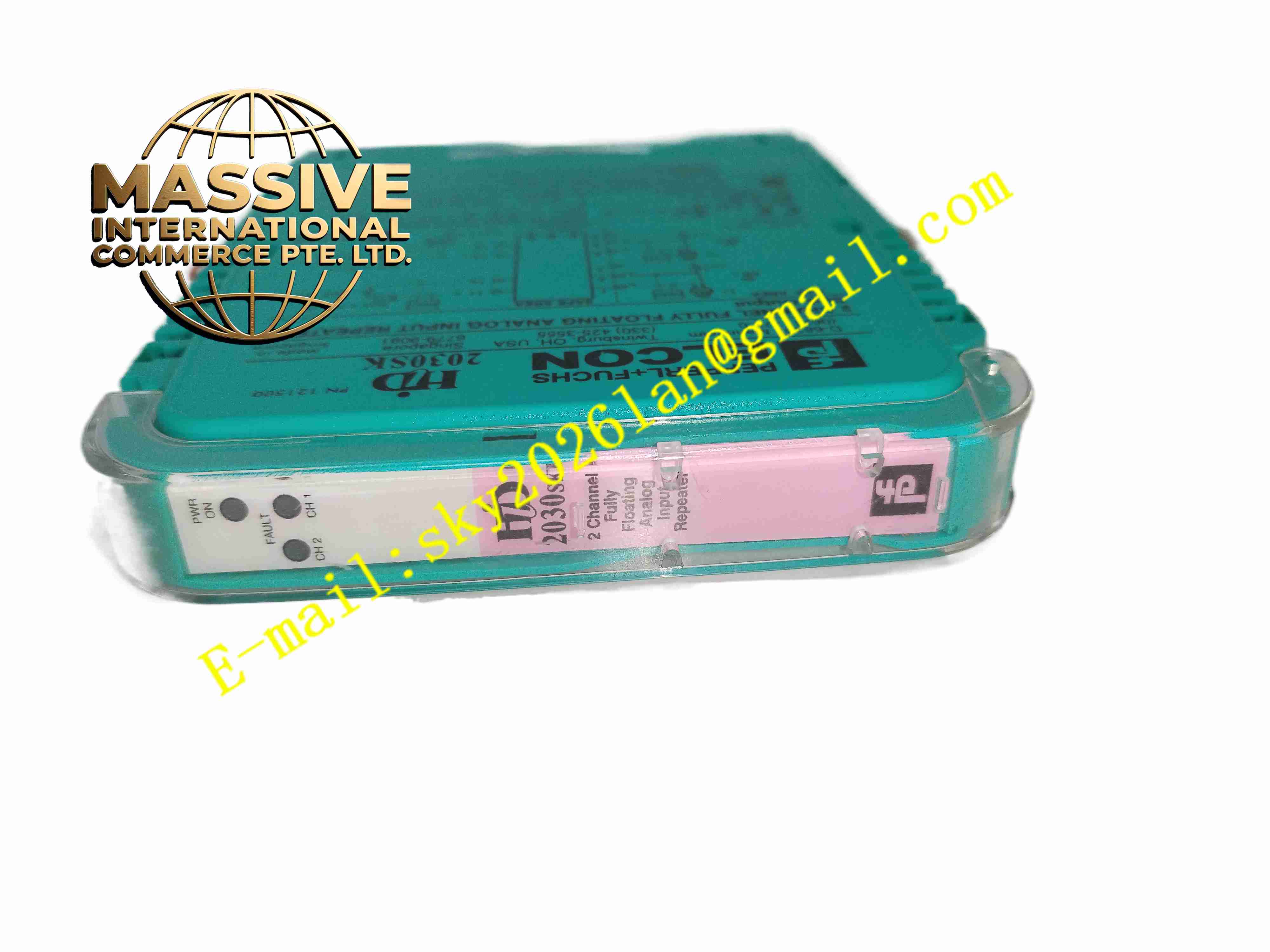
Pepperl+Fuchs HID2030
Technical Specifications
- Product Type: 2-channel SMART transmitter power supply isolated barrier
- Power Supply: 19 V DC to 30 V DC bus powered via termination board
- Field Side Output: Minimum 15.5 V DC at 20 mA for 2-wire transmitters
- Signal Range: 4 mA to 20 mA analog current signal
- Safe Side Output: Passive current sink output, load range 0 Ω to 650 Ω
- Isolation Voltage: 2.5 kV AC galvanic isolation
- Functional Safety: SIL 2, SC 3 according to IEC 61508
- Diagnostic Function: Line fault detection for wire break and short circuit
- HART Compatibility: Supports HART digital communication transmission
- Protection Rating: IP20
- Operating Temperature: -20 °C to +60 °C
- Mounting: Standard 35 mm DIN rail mounting
- Housing Width: 18 mm per module
Functional Features
- Regulated power supply for 2-wire HART SMART transmitters in intrinsically safe hazardous areas.
- 2 independent signal channels for two separate field transmitter loops.
- Galvanic isolation eliminates ground loop interference between field and control rack.
- Full pass-through of HART digital signal for remote parameter setting and diagnostic reading.
- Line fault detection continuously monitors field cable open circuit and short circuit faults.
- Passive current repetition outputs 4-20 mA signal to safe-side PLC analog input module.
- Compact slim DIN rail housing saves cabinet installation space.
- Removable screw terminal blocks simplify field wiring and maintenance.
- Built-in overvoltage and short-circuit protection safeguards field sensor circuit.
- Continuous self-test verifies internal safety circuit integrity during normal operation.
Application Scenarios
- Petrochemical plant hazardous zone 4-20mA pressure and temperature transmitter interface
- Refinery intrinsically safe field instrument signal isolation
- Offshore platform HART transmitter power and signal conditioning
- Chemical reactor flammable gas area analog signal transmission
- Pharmaceutical explosion-proof production area instrument loop safety barrier
Material Composition
- Housing: Flame-retardant polycarbonate plastic enclosure
- Main PCB: FR4 printed circuit board with conformal coating
- Isolation components: High isolation optocoupler and isolation transformers
- Power regulation components: Precision linear voltage regulator ICs
- Terminal blocks: Tin-plated copper alloy screw terminals
- Surge protection components: Transient suppression diodes and current limiting resistors
Structural Characteristics
- Slim single-width DIN rail plastic housing.
- Front panel LED indicators for power and channel fault status.
- Rear removable screw terminals separated into hazardous side terminals and safe side terminals.
- Internal physical isolation barrier separates intrinsically safe circuit and non-safe control circuit.
- Independent circuit design for each channel prevents cross-talk between two loops.
- Passive convection cooling without fan components.
Working Principle 24 V DC bus power supplies the HID2030 internal power regulation circuit. The module provides constant excitation voltage to 2-wire HART transmitters mounted in hazardous zone. The field transmitter outputs 4-20 mA current proportional to measured process variable. HID2030 repeats this analog current signal to the safe side while maintaining galvanic isolation. HART digital signal superimposed on the current loop passes through the barrier for remote configuration. Line fault detection circuit monitors loop impedance continuously and triggers fault indication for wire break or short circuit.
Installation Requirements
- Mount HID2030 on 35 mm DIN rail inside non-hazardous control cabinet only.
- Use shielded twisted pair intrinsically safe instrument cable for field transmitter wiring.
- Separate intrinsically safe wiring from non-safe power cables in cable trays.
- Complete protective earth connection to cabinet ground bar.
- Verify intrinsically safe loop calculation matches field transmitter parameters before commissioning.
- Perform 4-20mA signal test and line fault simulation test after wiring completion.
- Confirm ATEX / IECEx installation rules for hazardous area instrument wiring.
Usage Notes
- Do not modify internal safety components of the isolated barrier.
- Do not connect non-intrinsically safe power to field-side terminals.
- Keep cabinet environment free of corrosive gas and conductive dust.
- Inspect terminal screw tightness periodically under vibration conditions.
- Disconnect power before modifying intrinsically safe wiring.
- Use anti-static wristband when handling spare modules.
- Replace unit immediately when permanent isolation or power regulation fault occurs.