Description
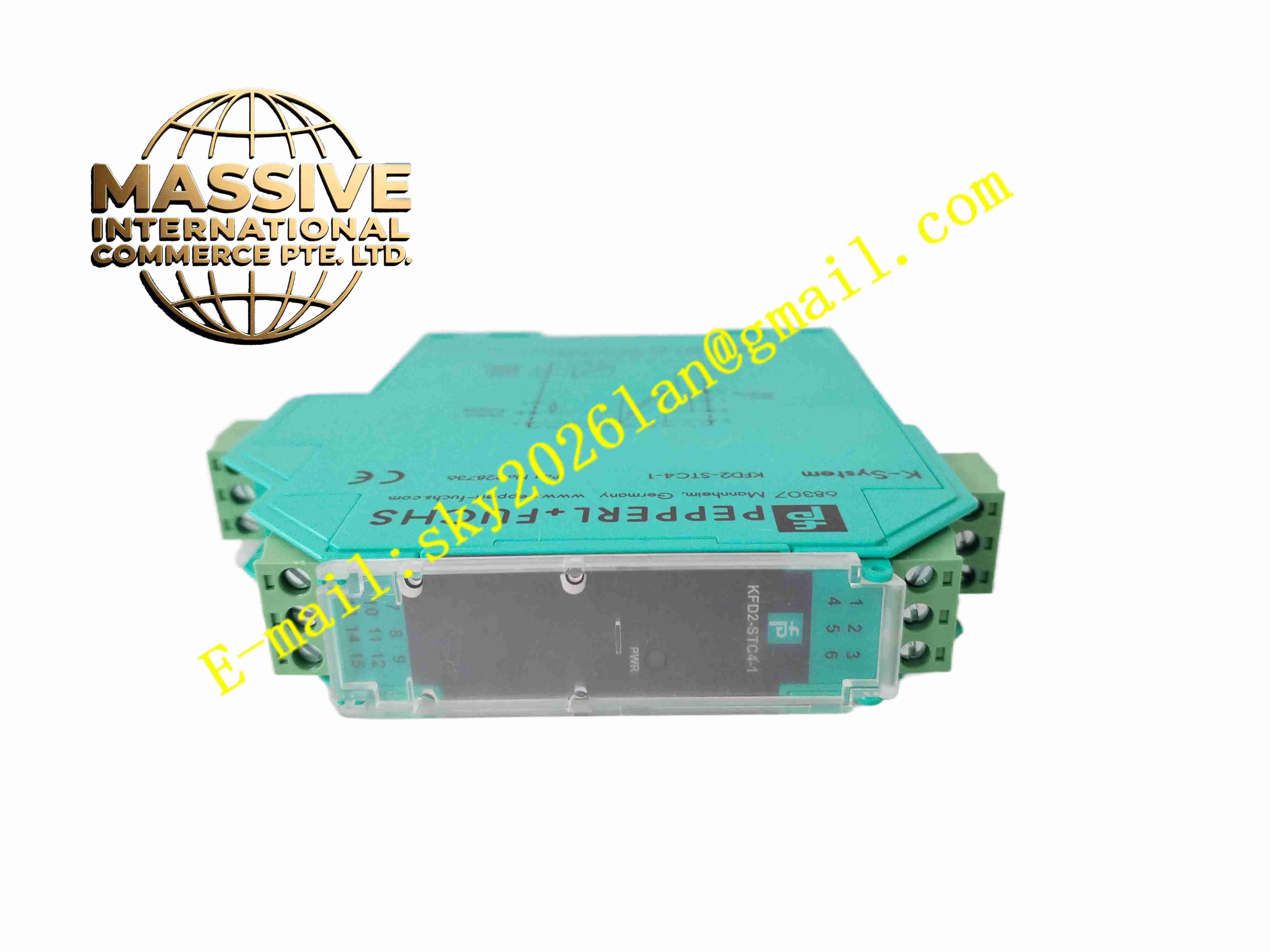
Pepperl+Fuchs KFD2-STC4-1
Technical Specifications
Signal type: Analog input
Channels: 1
Supply connection: Power Rail or terminals 14+, 15-
Rated supply voltage: 20 to 35 V DC
Power dissipation: 1.4 W
Power consumption: 1.8 W
Input signal: 0/4 to 20 mA
Input connection: terminals 1+, 2-, 3 or 5-, 6+
Voltage drop: ≤ 2.4 V at 20 mA on terminals 5, 6
Input resistance: ≤ 64 Ω on terminals 2-, 3; ≤ 500 Ω on terminals 1+, 3 including 250 Ω load
Available voltage for transmitter: ≥ 16 V at 20 mA on terminals 1+, 3
Output signal: 0/4 to 20 mA
Output connection: terminals 7-, 8+, 9
Output load: 0 to 800 Ω at 20 mA
Output ripple: maximum 50 µArms
Overload indication: above 25 mA
SIL rating: SIL 2
Communication support: HART, BRAIN, Foxboro SMART protocols
Ambient temperature: -20 to 60 °C
Mounting: 35 mm DIN rail
Connection type: screw terminals with test sockets
Functional Features
Single-channel isolated barrier for SMART transmitters
Loop power supply for 2-wire and 3-wire transmitters
4 to 20 mA analog signal transmission
HART communication pass-through
Galvanic isolation between field, supply, and output
Test sockets for loop checking and communicator connection
250 Ω HART communication resistor option
SIL 2 capability
Power Rail or terminal block supply
Compact K-System housing
Suitable for Zone 2 installation on the safe-area side
Application Scenarios
Pressure, temperature, level, and flow transmitter integration
HART-enabled field instrument connection
Process control systems requiring intrinsic safety barriers
Chemical and petrochemical plant instrumentation
Oil and gas field signal isolation
Pharmaceutical process monitoring
Water and wastewater treatment instrumentation
DCS/PLC analog input interfacing
Performance Parameters
Input range: 0/4 to 20 mA
Output range: 0/4 to 20 mA
Output load capability: 0 to 800 Ω at 20 mA
Transmitter supply voltage: ≥ 16 V at 20 mA
HART support: bidirectional digital communication on 4 to 20 mA loop
Isolation: galvanic isolation between input, output, and supply
SIL: 2
Supply voltage: 20 to 35 V DC
Power dissipation: 1.4 W
Ambient temperature range: -20 to 60 °C
Material Composition
Industrial thermoplastic K-System housing
Analog signal conditioning PCB
Loop power supply circuitry
HART communication filter network
Galvanic isolation stage
Screw terminal blocks with test sockets
Power Rail contact system
LED status indicators
DIN rail mounting clip
Internal protection components
Structural Features
K-System slim-line module
Front screw terminals for field and control wiring
Integrated test sockets for HART communicator
LED indicators for power and loop status
Power Rail compatible supply connection
Labeling area on front face
Compact DIN rail footprint
Robust industrial enclosure
Clear terminal numbering for wiring
Working Principle
The module supplies regulated loop power to a SMART transmitter connected on the field side. The transmitter modulates the loop current according to the measured process variable. The KFD2-STC4-1 reads this 4 to 20 mA signal, isolates it galvanically, and reproduces it on the safe-area output terminals. HART digital signals pass through the isolation barrier, allowing configuration and diagnostics without interrupting the analog signal. Test sockets provide access points for loop checks and communicator connection.
Installation Requirements
Install in a safe area or Zone 2 control cabinet
Mount on a 35 mm DIN rail
Connect 24 V DC supply to Power Rail or terminals 14+, 15-
Connect the transmitter to the field-side terminals according to 2-wire or 3-wire wiring
Connect the 4 to 20 mA output to the DCS/PLC analog input
Ensure loop load does not exceed 800 Ω at 20 mA
Use test sockets for HART communicator connection when required
Observe intrinsic safety wiring rules for hazardous area connections
Confirm ambient temperature is within -20 to 60 °C
Verify terminal tightness before commissioning
Usage Precautions
Do not exceed the output load limit of 800 Ω at 20 mA
Ensure HART communicator impedance is compatible with the loop
Verify transmitter voltage requirements against available loop voltage
Do not connect non-intrinsically safe devices to the field side unless certified
Keep hazardous area and safe area wiring separated
Use shielded cables for analog signals in noisy environments
Check test socket caps are closed when not in use
Confirm SIL requirements before using in safety functions
Replace only with Pepperl+Fuchs approved equivalents
Refer to the official datasheet and approval documents for final installation limits