Description
Pilz PSS SB DI80Z4 (301121) Digital Input Module
Technical Specifications Model: PSS SB DI80Z4, Part Number 301121 System Compatibility: Pilz PSS SB safety controller system Input Channel: Safety digital input channels Signal Type: 24VDC digital safety input Mounting Form: Plug-in module installation on PSS SB base rack Power Supply: 24VDC, supplied by rack backplane Operating Temperature: 0℃ ~ +60℃ Storage Temperature: -20℃ ~ +70℃ Relative Humidity: 10% ~ 90% non-condensing Safety Integrity Level: SIL3 Protection Grade: IP20 for module body Module Indicator: Channel LED indicator, module run and fault LED indicator
Functional Features Collects 24VDC digital safety signal from field safety components including safety switches and proximity sensors. Performs wire break and short circuit diagnosis for each safety input channel. Transmits safety input data to safety controller through safety bus with safe data transmission mechanism. Channel LED indicator displays real-time signal state of each input point. Module self-diagnosis continuously monitors hardware and communication state. Supports hot swap operation on safety rack. SIL3 safety level meets high-risk machinery safety protection requirement. Input signal filtering eliminates transient interference pulse from industrial field environment.
Application Scenarios Automotive production line safety control system, robot cell safety interlock, large packaging machine safety monitoring, press machine safety protection, logistics automated warehouse safety control system.
Performance Parameters Each input channel can detect open circuit and short circuit fault of field wiring. Safety bus communication transmits data with safety checksum verification to prevent data distortion. Module keeps stable signal acquisition under mechanical vibration of production line. Self-diagnosis circuit detects hardware abnormality and triggers fault indication immediately. Channel LED reflects input signal state without delay. Module can continuously run for long time under rated cabinet temperature.
Material Composition Module housing: Black flame-retardant engineering plastic. Main PCB: FR4 multi-layer industrial printed circuit board with conformal coating. Core electronic components: Safety logic processing chip, input optocoupler isolation component, transient protection chip, bus communication chip, memory chip. Connector: Gold-plated backplane edge connector for safety rack base. Terminal block: Screw terminal block for field signal wiring. Indicator components: Channel status light emitting diodes. Fasteners: Plastic positioning buckle.
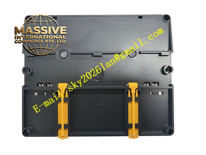
Structural Features Rectangular plug-in module structure matching PSS SB safety rack slot. Front panel equipped with LED indicators for each input channel and module status. Screw terminal block on front for field sensor wiring. Gold-plated edge connector on rear side for connection with rack backplane safety bus. Internal circuit adopts isolation design between field input circuit and safety bus circuit. Module side positioning buckle ensures accurate insertion and locking on rack slot. Natural convection heat dissipation through ventilation slots on plastic housing.
Working Principle The module obtains 24VDC working power from rack backplane. Field 24VDC safety digital signal enters module through front screw terminal block. Optocoupler component isolates field signal from internal safety logic circuit. The safety processing chip collects input signal state and carries out wire break and short circuit diagnosis for each channel. Valid input data adds safety checksum, then transmits to PSS SB safety controller through safety backplane bus. The controller uses these safety signals for safety logic judgment. Module self-diagnosis circuit monitors chip operation, power supply and bus communication state all the time. Fault indicator lights up once hardware failure or bus communication interruption occurs.
Installation Requirements Cut off rack power supply before installing or removing module. Align module with empty slot of Pilz PSS SB safety rack, push inward until backplane connector fully inserts and buckle locks. Connect field safety sensor wiring to front screw terminals according to channel definition. Power on the safety rack after wiring completion. Complete module hardware recognition and channel parameter configuration in Pilz safety programming software. Test each input channel signal acquisition function. Keep module inside control cabinet and reserve ventilation space around module.
Usage Precautions Module can only be used with matched Pilz PSS SB safety control rack. Cut off rack main power before plugging or unplugging module. Use shielded cable for long-distance field sensor wiring. Do not exceed rated input voltage of each channel. Avoid installation environment with condensation and corrosive gas. Regularly check terminal screw tightness and wiring integrity during maintenance. Do not open module housing without professional authorization. Replace module immediately if persistent channel fault occurs.