Description
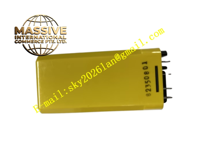
Potter & Brumfield SDAS-01-7Y2S1024
Technical Specifications Brand: Potter & Brumfield Model: SDAS-01-7Y2S1024 Input Control Voltage: 3-32 VDC Output Load Type: AC load Rated Output Voltage: 24-280 VAC Rated Load Current: 24 A Zero-crossing turn-on circuit Operating Temperature: -30°C to +80°C Mounting: Panel mounting with heat sink Isolation: 2500 Vrms between input control side and output load side
Functional Features Non-contact semiconductor switching without mechanical contact wear. Zero-crossing switching function reduces inrush current and electrical arc during switching. High-speed on-off operation suitable for frequent switching cycles. Built-in overvoltage and overcurrent protection circuit. High isolation strength separates low-voltage control signal and high-voltage AC load circuit. Compact integrated assembly structure simplifies cabinet layout.
Application Scenarios Heater control for industrial ovens, packaging machine actuator control, lighting system switching, HVAC equipment control, automated test bench load switching.
Performance Parameters No mechanical bounce during switching action. Low leakage current at off-state. Strong resistance to vibration and mechanical shock. Consistent switching performance after millions of operation cycles. Low electromagnetic interference compared with mechanical relay.
Material Composition Housing: High-temperature flame retardant thermoplastic. Power Semiconductor Chip: Thyristor silicon chip. PCB: FR4 printed circuit board. Heat Sink: Aluminum alloy heat dissipation base. Terminals: Tin-plated copper screw terminals.
Structural Features Rectangular integrated module structure. Aluminum heat sink at bottom for heat dissipation of power semiconductor. Front side equipped with input control terminals and output load terminals. Internal potting compound encapsulates circuit components to resist vibration and moisture. Mounting holes on heat sink base for panel fixing.
Working Principle When DC control signal is applied to input terminals, the optocoupler inside the module triggers thyristor conduction. The AC load circuit turns on at AC voltage zero crossing point. When input control signal disappears, thyristor cuts off at AC current zero crossing point. There are no moving mechanical parts in the whole switching process. Protection components suppress surge voltage on load circuit.
Installation Requirements Mount module onto metal heat dissipation panel with mounting screws. Tighten all terminal screws with specified torque. Wire control signal and AC load circuit separately. Ensure sufficient air flow around heat sink. Add external snubber circuit when switching inductive load.
Usage Notes Do not exceed rated load current and voltage. Do not apply DC voltage to AC output terminals. Check heat sink temperature during continuous heavy load operation. Prevent overheating caused by poor heat dissipation. Keep module surface clean from dust.