Description
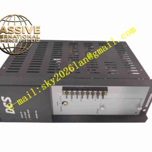
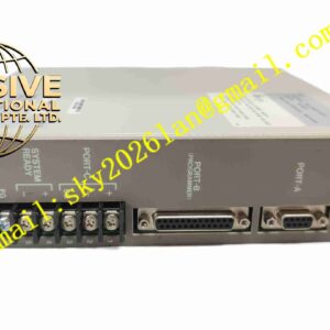
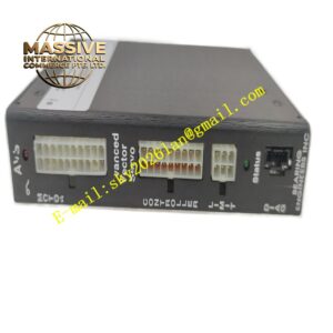
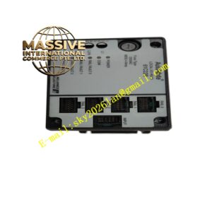
RELIANCE ELECTRIC S-D4007
Technical Specifications Brand: Reliance Electric Model: S-D4007 Board Type: Power interface PCB Operating Supply: 24 VDC control power Signal Interface: Analog feedback signals, digital fault I/O Operating Temperature: 0°C to +60°C Humidity: 5% to 95% non-condensing Mounting: Rack plug-in board inside drive cabinet Insulation: Reinforced isolation between low voltage logic and power circuits
Functional Features Transmit motor current and voltage feedback signals from power stage to main controller. Distribute low-voltage control power to each functional sub-board inside drive unit. Capture hardware fault signals including overcurrent, over-temperature and power loss and forward to main control board. Opto-isolation separates high-power power circuit and low-voltage logic circuit. Onboard status indicator LEDs display real-time working and fault state. Filter circuits suppress electrical noise generated by power switching devices.
Application Scenarios Heavy industry variable speed AC/DC drive systems, paper mill motor control, metal rolling production line drives, mining conveyor motor regulation, large pump and fan variable speed control.
Performance Parameters High noise immunity in high power switching cabinet environment. Fast fault signal transmission response when drive abnormality occurs. Stable long-term signal transmission under continuous vibration. Isolation circuit blocks high voltage surge from power section to logic control circuit. Consistent signal conversion precision for motor feedback parameters.
Material Composition PCB Substrate: FR4 multilayer printed circuit board with conformal coating. Front Panel: Flame retardant black plastic with LED indicators. Core Components: Optocouplers, signal conditioning resistors and capacitors, transient protection diodes. Edge Connector: Gold-plated edge connector for backplane connection. Terminal Blocks: Screw clamp plastic terminal blocks for external wiring.
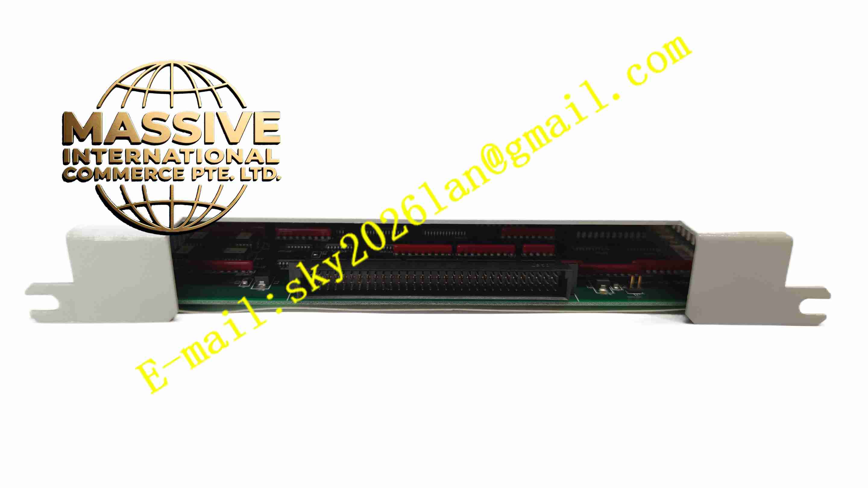
Structural Features Vertical plug-in board form factor for installation inside drive cabinet rack. Front plastic panel holds LED status indicators. Rear gold finger edge connector mates with drive internal backplane. Internal PCB layout physically partitions high voltage power traces and low voltage signal traces. Side locking tabs fix the board in rack slot.
Working Principle Control power feeds onto the board from drive internal power supply. Current and voltage feedback signals from power module enter signal conditioning circuit. Optocouplers provide galvanic isolation and convert raw power stage signals into logic-level signals for main controller. Fault detection circuit continuously monitors power circuit status and sends fault trigger signals to main control board once abnormal condition appears.
Installation Requirements Cut off all AC and DC power supply of drive cabinet before inserting the board. Align gold finger connector with backplane slot and insert fully. Lock side tabs to secure the board. Check all wiring terminals and backplane connection. Restore cabinet ventilation after installation.
Usage Notes Wear anti-static wristband during board replacement. Confirm drive power fully discharged before opening cabinet cover. Do not touch PCB traces and components directly. Regularly inspect conformal coating for peeling or corrosion in humid environments. Clean dust accumulation on board surface periodically.