Description
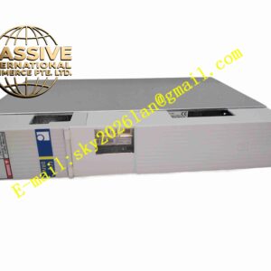
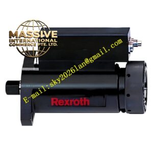
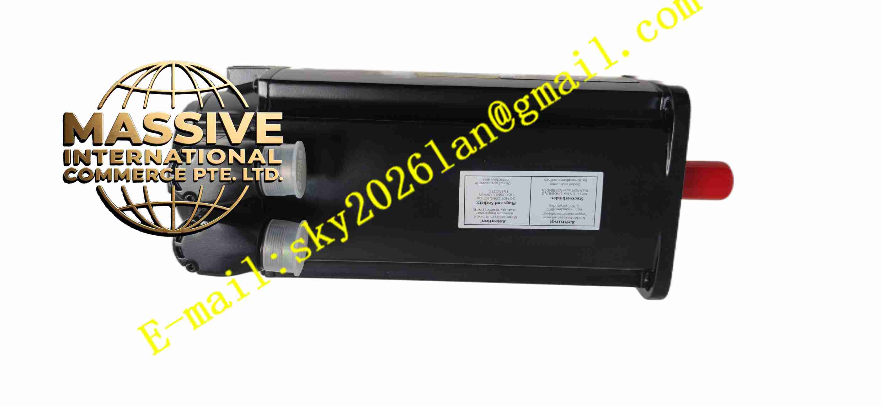
Rexroth R911317019
Technical Specifications Model: R911317019 Brand: Bosch Rexroth Mounting Style: DIN rail or cabinet rack installation Power Interface: Three-phase AC power input Feedback Interface: Encoder signal input for servo motor Communication: Industrial fieldbus interface for controller connection Operating Temperature: 0 ℃ ~ +55 ℃ Storage Temperature: -40 ℃ ~ +85 ℃ Relative Humidity: 5% ~ 90%, non-condensing Protection Class: IP20 Control Mode: Torque control, speed control, position control Internal Protection: Overvoltage, undervoltage, overcurrent, overtemperature, motor overload protection
Functional Features Supports three core closed-loop control modes including torque, speed and position. High dynamic current loop ensures fast response for motor torque adjustment. Built-in encoder signal processing circuit reads motor position and speed feedback data in real time. Complete hardware protection system triggers output shutdown once fault condition is detected. Industrial bus communication realizes real-time data exchange with upper control system. Parameter storage function saves drive configuration parameters inside onboard memory. Fault diagnosis and alarm function record fault codes for equipment maintenance. Pulse and direction command input is available for connection with traditional motion controllers.
Application Scenarios Machine tool feed axis control, packaging machinery motion system, material handling automation equipment, textile machinery drive system, metal forming equipment, automated assembly lines, robotic auxiliary axis driving.
Performance Parameters The current loop maintains high response speed to suppress torque fluctuation during dynamic operation. Position control loop achieves high positioning accuracy under rated load. Drive hardware keeps stable operation under continuous long-time running. Fault protection circuit cuts off power output instantly when abnormal electrical status occurs. Fieldbus communication maintains stable real-time data transmission under industrial electromagnetic environment. Parameter memory retains all configuration data after power outage.
Material Composition Main Housing: Black flame-retardant engineering plastic front shell and metal shielding frame. Main PCB: FR4 multi-layer industrial printed circuit board coated with conformal protective coating. Core Electronic Components: IGBT power modules, current sampling resistors, encoder receiving chips, FPGA, flash memory, power management IC, transient voltage suppression components. Connector: Gold-plated power terminal blocks, signal terminal blocks and bus connectors. Indicator Components: LED indicators for power, running status and fault alarm. Fasteners: Stainless steel screws and metal fixing clips.
Structural Features Compact rectangular cabinet-mounted structure. Front panel integrates LED status indicators and operation buttons for parameter setting. Metal shielding frame surrounds internal circuit board to reduce electromagnetic emission and external interference. Rear area is equipped with power terminals, motor output terminals and signal terminals. Internal circuit separates high-power power conversion circuit and low-voltage signal processing circuit. Ventilation slots are reserved on housing for natural and forced convection heat dissipation.
Working Principle Three-phase AC power enters the module through power terminals. Internal rectifier circuit converts alternating current to DC bus voltage. IGBT power inverter circuit converts DC bus voltage into variable-frequency variable-amplitude AC power to drive servo motor. The encoder mounted on servo motor feeds back rotor position and speed signal to the drive module. The onboard control chip compares the feedback signal with the target command value sent by upper controller, calculates control deviation and adjusts inverter output in closed loop. The module continuously monitors bus voltage, output current and internal temperature. When parameters exceed rated threshold, protection circuit shuts down power output and activates fault LED indicator. All running data and fault information can be uploaded to upper controller through fieldbus.
Installation Requirements Cut off the main power supply before installing or removing the module. Mount the module inside closed electrical cabinet on DIN rail or rack bracket, lock fixing components firmly. Connect three-phase power cable, motor power cable and encoder feedback cable to corresponding terminals strictly according to wiring diagram. Use shielded cables for encoder signal wiring, single-point grounding of shielding layer. Keep enough clearance around the module for heat dissipation, do not block ventilation slots. Complete parameter configuration via Rexroth dedicated commissioning software after wiring. Power on the system and perform static and dynamic test before putting into formal production.
Usage Precautions Do not apply input voltage beyond rated range to power terminals. Ensure reliable protective earth grounding of module housing for safety and EMC performance. Keep signal cables away from high-power AC cables to reduce electromagnetic coupling interference. Do not operate in environment with condensation, corrosive gas or conductive dust. Do not disassemble module housing without professional authorization, internal power components carry high voltage after power off. Back up drive parameters before firmware upgrade or maintenance operation. Cut off main power and wait for DC bus discharge before touching internal terminals.