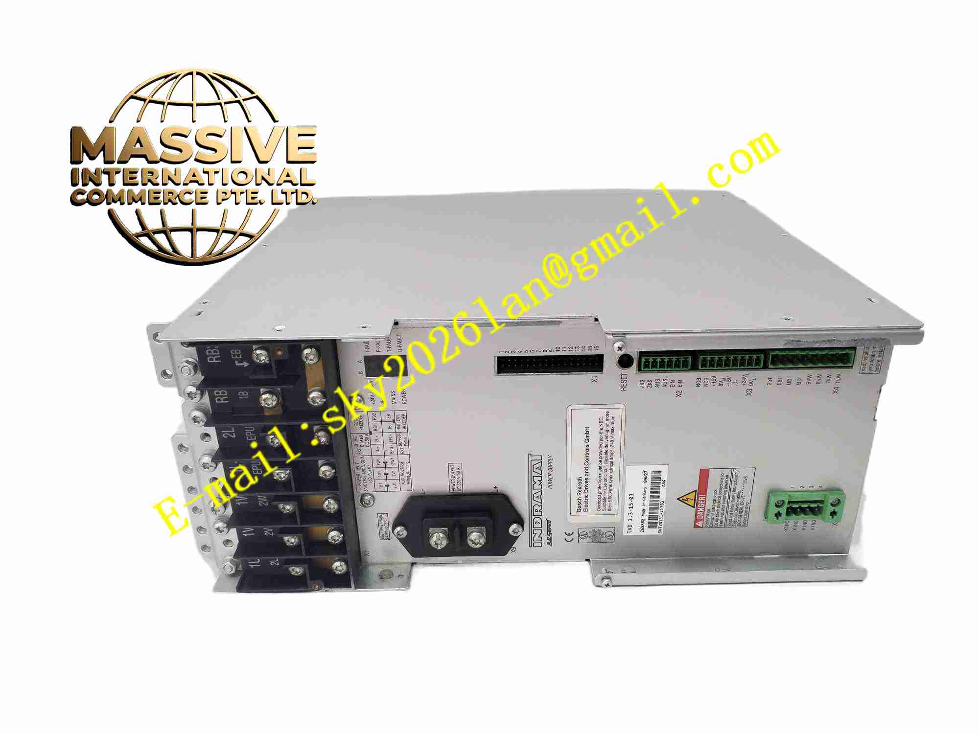
Description
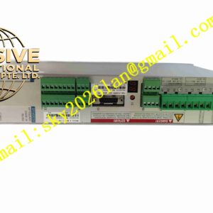
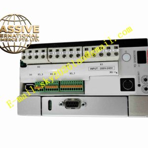
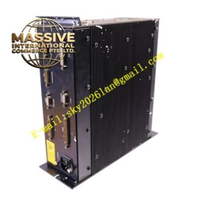
Rexroth TVD1
Technical Specifications
- Brand: Bosch Rexroth / Indramat
- Series: TVD power module family
- Model family: TVD1
- Product type: Power supply module / braking module
- Typical variant: TVD1.3-15-03
- Typical power rating: Around 15 kW for TVD1.3-15-03
- Typical DC bus voltage: Around 320 V for TVD1.3-15-03
- Input: Three-phase AC mains, depending on sub-model
- Mounting: Drive rack or control cabinet mounting
- Cooling: Air cooling
- Monitoring: DC bus monitoring and fault indication
Functional Features
- Supplies or supports DC bus power for Rexroth / Indramat drives.
- Handles regenerative energy during motor deceleration.
- Supports external braking resistor connection in applicable variants.
- Provides DC bus voltage stabilization for multi-axis drive systems.
- Includes monitoring and fault signaling functions.
- Compatible with Indramat controllers and servo inverter modules.
- Modular design supports system expansion and maintenance.
Application Scenarios
- Servo drive systems with frequent acceleration and deceleration.
- CNC machine tools and spindle drives.
- Printing and packaging machinery.
- Woodworking machinery and metal forming machines.
- Conveyor systems with high inertia loads.
- Test rigs and special-purpose motion systems.
- Industrial automation systems using Rexroth / Indramat drives.
Performance Parameters
- Power rating: Approximately 15 kW for TVD1.3-15-03.
- DC bus voltage: Approximately 320 V for .3-15-03.
- Braking function: Supports regenerative energy handling in applicable variants.
- Monitoring: DC bus voltage supervision and fault indication.
- Exact input voltage range, continuous braking power, resistor specifications, current rating and response times depend on the specific sub-model.
Material Composition
- Industrial-grade PCB assembly
- Rectifier and DC bus circuitry
- Braking chopper or braking control circuit
- Power resistors or external resistor interface
- Monitoring and protection electronics
- Metal heat sink or chassis structure
- Terminal blocks and connector interfaces
- Status indicators and module label
Structural Features
- Modular industrial drive module design.
- Terminals for mains input, DC bus and braking resistor where applicable.
- Status indicators for power, braking and fault conditions.
- Designed for rack or cabinet mounting within Rexroth / Indramat drive systems.
- Compact layout for integration with inverter and controller modules.
- Exact dimensions and connector positions depend on the specific sub-model.
Working Principle
The module participates in DC bus power management for Rexroth / Indramat drive systems. During normal operation, it helps maintain a stable DC bus voltage. When servo motors decelerate or lower heavy loads, regenerative energy returns to the DC bus. The module monitors the DC bus voltage and, when necessary, dissipates excess energy through braking resistors or braking circuits. This prevents overvoltage faults and allows controlled deceleration of the drive system.
Installation Requirements
- Install in a ventilated control cabinet or drive rack.
- Confirm that the sub-model matches the system voltage and power requirements.
- Use correctly sized cables for mains, DC bus and braking resistor connections.
- Ensure reliable protective earth connection.
- Maintain required clearance around heat-generating components.
- Verify braking resistor rating and wiring if an external resistor is used.
- Check module status indicators after power-up.
- Refer to the official Rexroth / Indramat manual for exact wiring and configuration.
Precautions for Use
- Do not exceed the rated DC bus voltage or braking power.
- Verify braking resistor specifications before operation.
- Investigate overvoltage or braking faults before restarting the machine.
- Disconnect mains power before maintenance or module replacement.
- Avoid installation near excessive heat, dust or moisture.
- Ensure compatibility with connected inverter and controller modules.
- Specific fault codes, resistor values and commissioning steps should follow the official Rexroth documentation.