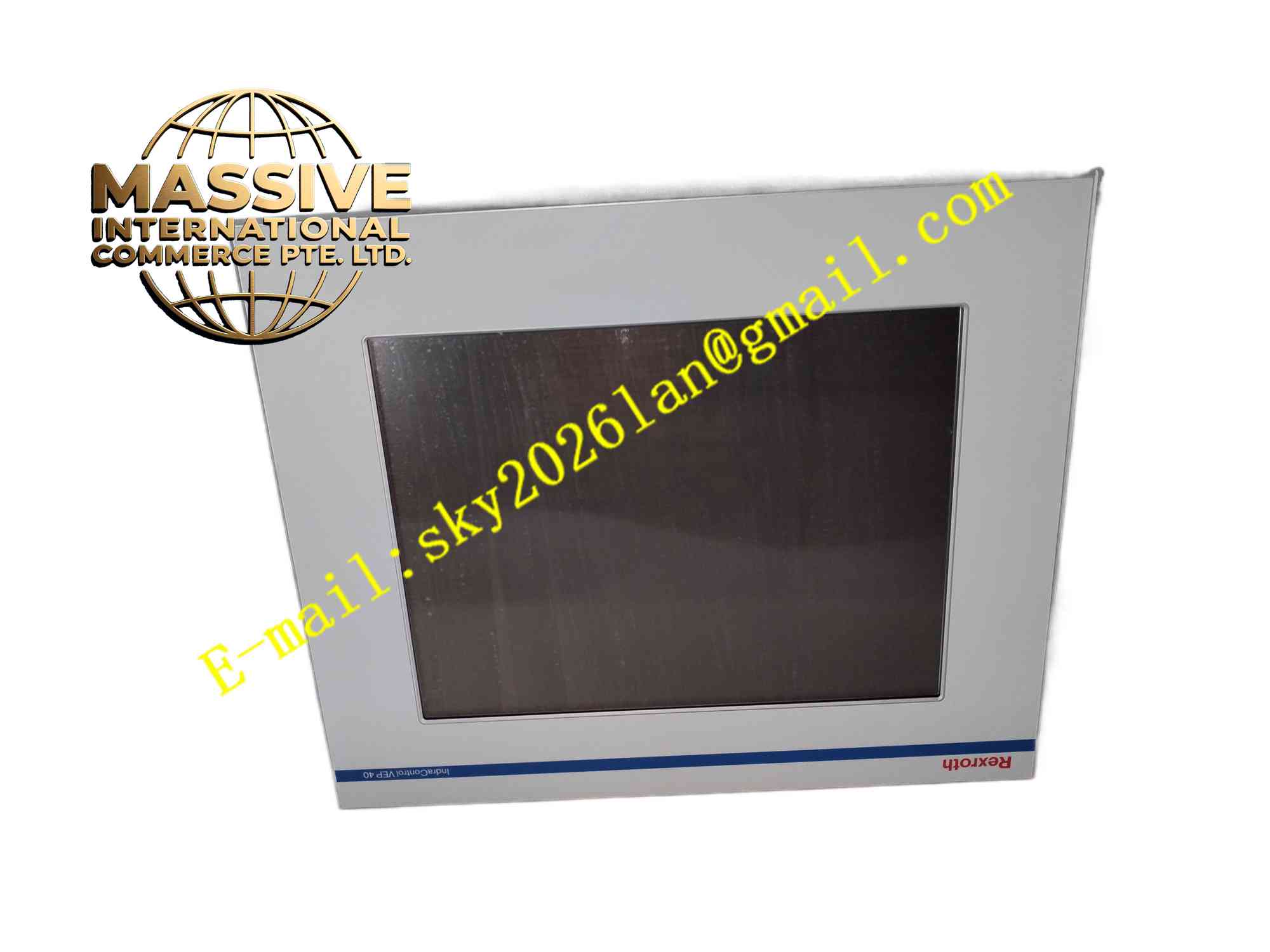
Description
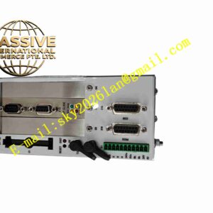
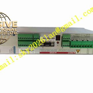
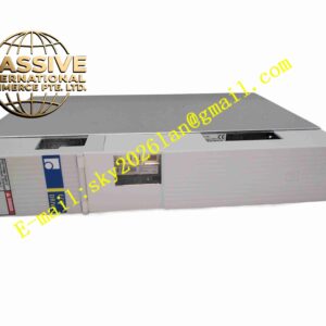
Rexroth VEP40.5 R911172936
Technical Specifications: Part number: R911172936 Model: VEP40.5 Input: Three phase AC mains power Output: Regulated DC bus for servo inverters Rated power: 40kW Pre-charge circuit: Integrated DC bus pre-charge function Brake resistor connection: External braking resistor interface Power device: IGBT and rectifier diodes Operating temperature: 0℃ to +55℃ Protection functions: Overvoltage, undervoltage, overcurrent, overtemperature Mounting: Cabinet chassis mounting
Functional Features: Three phase AC to DC power conversion for shared servo DC bus. Integrated pre-charge circuit to limit inrush current during power on. Interface for external braking resistor to dissipate regenerative energy. Multiple hardware protection functions including overvoltage, overcurrent and overtemperature. DC bus voltage monitoring and fault signal output to servo controller. Cooling fan for internal power semiconductor heat dissipation. DC bus terminal for connection to multiple servo axis inverters.
Application Scenarios: Multi-axis metal forming machine, printing machinery main drive, packaging line servo system, machine tool multi-axis motion control, textile heavy duty servo drive, handling robot multi-axis servo cabinet.
Performance Parameters: Stable DC bus voltage output under dynamic regenerative load. High overload withstand capability during machine acceleration. Fast hardware protection response for fault condition. High power conversion efficiency for continuous operation.
Material Composition: Copper insulated metal substrate PCB for power circuit. High power rectifier diodes and IGBT semiconductor components. Aluminum alloy heat sink with cooling fan assembly. High current copper busbars. Electrolytic and film DC bus capacitors. High voltage plastic insulated terminal blocks. Metal coated housing with EMC shielding.
Structural Features: Vertical chassis mount power module. High current busbar terminals for three phase AC input and DC bus output. Screw terminals for braking resistor wiring and fault signal output. Built-in cooling fan and air flow channel for heat dissipation. Internal partition separates high power main circuit and low voltage signal circuit.
Working Principle: Three phase AC mains power enters VEP40.5 module. Pre-charge circuit activates first to charge DC bus capacitors gradually and limit inrush current. After pre-charge completes, main rectifier circuit switches on and converts AC to DC voltage. Stabilized DC bus power supplies multiple servo inverters connected on shared bus. When servo motor returns regenerative energy back to DC bus during deceleration, excess energy dissipates on external braking resistor. Onboard monitoring circuit detects DC bus voltage, output current and internal temperature, triggers hardware protection and fault signal output once threshold exceeded.
Installation Requirements: Mount module vertically inside industrial control cabinet. Connect three phase AC input and DC bus busbar with specified torque. Wire external braking resistor to dedicated terminal. Separate high power main wiring and low voltage signal wiring. Ensure cabinet cooling air flow meets module requirement. Perform residual DC bus discharge before cabinet maintenance.
Usage Notes: Verify mains input voltage matches module rated specification. Select braking resistor resistance and power rating according to machine regenerative energy. Check cooling fan operation after power on. Release DC bus residual charge before opening cabinet cover. Inspect busbar terminals and capacitor temperature periodically during maintenance.