Description
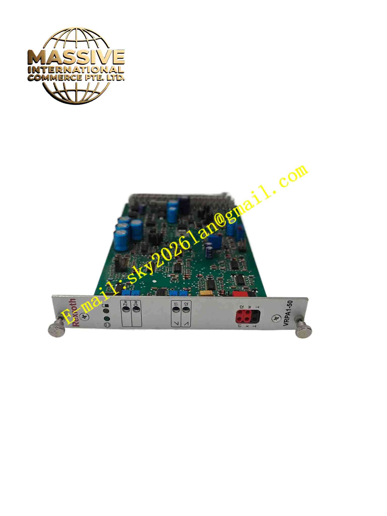
Rexroth VT-VRPA1-50-1X R900952202
Technical Specifications
- Product type: Proportional valve amplifier card
- Supply voltage: DC24 V
- Input signal: 0 to ±10 V or 4 to 20 mA
- Output current: Up to 1.5 A per solenoid
- Number of channels: 2
- Dither frequency: Adjustable
- Ramp time: Adjustable
- Gain and offset: Adjustable via potentiometers
- Operating temperature: 0 °C to +55 °C
- Storage temperature: -20 °C to +85 °C
- Humidity: 5 % to 95 %, non-condensing
- Protection: IP20
- Mounting: DIN rail
- Short-circuit protection: Output short-circuit protected
Functional Features
- Dual-channel proportional solenoid current control
- Adjustable ramp generator for smooth acceleration
- Dither signal to reduce solenoid static friction
- Adjustable gain and offset
- Current feedback closed-loop control
- Output short-circuit protection
- Front panel potentiometers and LEDs
- Compatible with Rexroth proportional valves
- High current stability
- Industrial hydraulic environment
Application Scenarios
- Injection molding machine proportional valve control
- Machine tool hydraulic axis control
- Metallurgical press hydraulic system
- Forging press proportional pressure regulation
- Mobile industrial hydraulic equipment
Materials and Construction
- Housing: DIN rail plastic or metal mounting frame
- PCB: FR4 board
- Output stage: Power transistor with current sense
- Potentiometers: Precision multi-turn potentiometers
- Terminals: Screw terminals
- Passive components: Capacitors, resistors
- LED: Status indicator
Structural Features
- PCB mounted in DIN rail enclosure
- Front panel potentiometers and LEDs
- Screw terminals for supply, setpoint, and solenoid
- Internal power supply, input conditioning, and output stage
- Current sense resistor in solenoid return path
- DIN rail mounting clip
- Compact board design
Working Principle The external setpoint voltage is compared with actual solenoid current measured by the current sense resistor. The error amplifier drives the output power transistor to adjust solenoid current until measured current equals the setpoint command. The ramp generator limits setpoint rate of change to prevent hydraulic shock. A high-frequency dither signal is superimposed on the current to keep the solenoid moving freely. Potentiometers set gain, offset, ramp time, and dither amplitude.
Installation Requirements
- Mount on 35 mm DIN rail inside hydraulic control cabinet
- Use shielded cable for setpoint signal
- Use shielded cable for solenoid leads
- DC24 V supply with sufficient current rating
- Separate signal cables from solenoid cables
- Temperature 0 °C to +55 °C
- Set ramp, gain, and offset after power-up
- Connect cabinet protective ground
Precautions
- Solenoid resistance must match amplifier output rating
- Do not short solenoid output terminals during operation
- Set ramp time to avoid hydraulic pressure spikes
- Verify current direction for proportional valves with two solenoids
- Keep cabinet free of hydraulic oil contamination
- Store spare card in anti-static packaging
- Periodically clean potentiometer contacts
- Do not exceed maximum solenoid current rating