Description
ROLLS-ROYCE H1127-0101
Technical Specifications
- Product Type: Turbine speed measurement interface PCB assembly
- Input Signal: Magnetic pickup probe sine wave pulse signal
- Speed Measurement Range: 0 to 20000 RPM
- Input Frequency Range: 10 Hz to 20 kHz
- Power Supply: 24 V DC
- Communication Interface: Proprietary parallel backplane bus to turbine controller
- Diagnostic Functions: Probe wire break, short circuit, low amplitude signal detection
- Protection Rating: Board assembly IP00, cabinet mounted IP20
- Operating Temperature: 0 °C to +60 °C
- Mounting: Rack plug-in slot module
- Cooling: Passive convection cooling
Functional Features
- Waveform conditioning and shaping for low amplitude magnetic pickup probe pulse signals.
- High resolution shaft rotational speed calculation from pulse frequency.
- Dual channel speed input supports redundant speed probe configuration for overspeed protection.
- Continuous probe health diagnostic detects open circuit, short circuit and weak signal.
- Speed value and fault status transmit to turbine controller via rack backplane bus.
- Front panel LED indicators display power, speed signal presence and probe fault.
- Galvanic isolation protects speed measurement circuit from field electrical noise.
- Conformal coated PCB adapts to power plant and marine cabinet environment.
- Overspeed signal pre-processing supports fast response for turbine protection logic.
- Hot swap capability for replacement during planned maintenance shutdown.
Application Scenarios
- Gas turbine shaft speed measurement and overspeed protection
- Marine propulsion turbine speed governor signal interface
- Power plant combined cycle gas turbine speed monitoring rack
- Offshore platform gas turbine redundant speed probe signal conditioning
- Heavy duty industrial turbine shaft condition monitoring
Material Composition
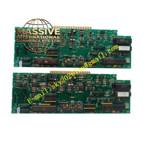
- Main PCB: FR4 high reliability printed circuit board with conformal coating
- Signal processing components: Comparator chips, pulse counter ICs
- Isolation components: Optocoupler isolation chips
- Backplane connector: Gold-plated copper edge contact pins
- Passive components: Precision resistors and capacitors for signal filtering
- Front panel: Flame-retardant polycarbonate plastic with LED windows
Structural Characteristics
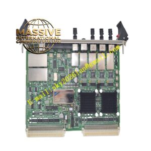
- Plug-in rack module PCB with front locking lever and LED indicator panel.
- Rear gold-plated edge connector inserts into turbine control rack backplane.
- Dual independent speed input channels for redundant magnetic probes.
- Internal signal filtering circuit suppresses electrical noise from turbine ignition systems.
- Internal circuit layout separates low level probe signal circuit and digital logic circuit.
- Conformal coating protects PCB surface against moisture and airborne contaminants.
Working Principle Magnetic speed probe generates sine wave pulse signal proportional to turbine shaft rotational speed. H1127-0101 receives weak sine wave signal, filters noise and shapes waveform into square pulse. Internal counter calculates pulse frequency and converts frequency value to shaft RPM. Diagnostic circuit monitors signal amplitude and loop impedance to detect probe failure. Measured speed value and fault status transmit to turbine main controller via backplane bus. Controller uses speed data for governor closed-loop control and overspeed protection trip logic.
Installation Requirements
- Insert H1127-0101 module into designated slot of Rolls-Royce turbine control rack.
- Use shielded twisted pair cable for magnetic speed probe wiring.
- Separate speed probe cables from high voltage ignition and motor power cables.
- Complete protective earth connection for rack and control cabinet.
- Adjust probe air gap on turbine shaft according to turbine manual specification.
- Perform speed signal simulation test and probe fault simulation test after wiring completion.
- Inspect backplane connector contact integrity before power energization.
Usage Notes
- Do not modify speed probe wiring during turbine running.
- Keep cabinet dry and free of oil mist and conductive dust.
- Inspect speed probe cable tightness periodically under turbine vibration environment.
- Execute periodic overspeed loop proof test according to turbine maintenance schedule.
- Disconnect field probe wiring before high voltage insulation resistance test.
- Use anti-static wristband when handling spare board.
- Replace board immediately when permanent speed signal conditioning fault occurs.