Description
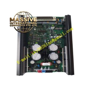
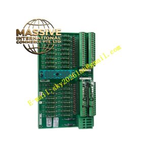
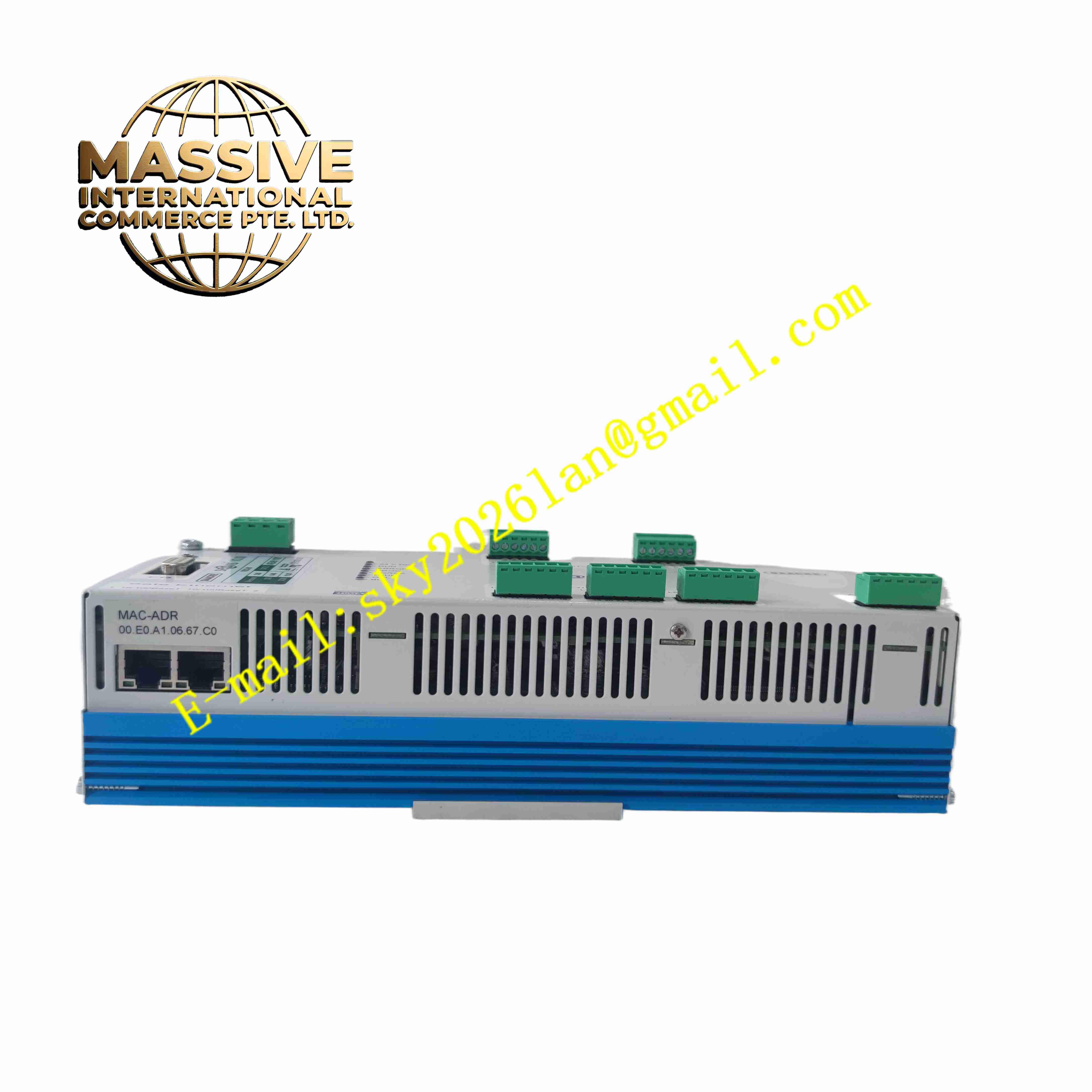
SAACKE FSC-01
Technical Specifications
- Product Type: Combustion safety controller
- Power Supply: 24 V DC
- Power Consumption: 20 W
- Digital Input Channels: 8 × 24 V DC interlock and status signals
- Analog Input Channels: 4 × 0-10 V or 4-20 mA for process transmitters
- Digital Output Channels: 8 × relay output, rated 250 V AC / 5 A
- Analog Output Channels: 2 × 4-20 mA for damper and VFD control
- Control Algorithms: PID, cascade control, fuel-air ratio control
- Communication Interface: RS-485 Modbus RTU, optional Ethernet Modbus TCP
- Safety Certification: IEC 61508 SIL3
- Protection Rating: IP20 for control unit
- Operating Temperature: -20 °C to +60 °C
- Storage Temperature: -30 °C to +70 °C
- Relative Humidity: 5 % to 95 %, non-condensing
- Mounting Dimensions: 200 × 150 × 80 mm, wall mounting
- Net Weight: 2 kg
Functional Features
- Complete burner sequencing control including pre-purge, ignition, flame monitoring and post-purge.
- Continuous flame signal evaluation to detect flame loss and trigger immediate safety trip.
- Closed-loop fuel-air ratio regulation reduces excess air and lowers NOx emission.
- 8 relay outputs drive fuel shutoff valves, fan contactors and alarm indicators.
- Built-in interlock logic validates pressure, temperature and limit switch status before ignition.
- Modbus communication uploads combustion parameters, fault codes and operating status to DCS.
- Integrated event log records trip time, fault type and process snapshot for troubleshooting.
- Hardware safety circuit independently cuts fuel supply upon detected unsafe conditions.
- Parameter lock function prevents unauthorized modification of burner configuration.
- Self-diagnostic test runs automatically at power-up and continuous background monitoring during operation.
Application Scenarios
- Industrial steam boiler and hot water boiler burner control
- Refinery process heater and furnace combustion safety system
- Power plant auxiliary boiler dual-fuel burner management
- Waste heat recovery furnace fuel and air regulation
- Marine boiler combustion safety control system
Material Composition
- Housing: Flame-retardant ABS plastic enclosure
- Main PCB: FR4 printed circuit board with conformal coating
- Relay components: Industrial electromagnetic safety relays
- Signal processing chips: High precision analog front-end and safety logic processors
- Terminal blocks: Tin-plated copper alloy screw terminals
- Internal connectors: Gold-plated copper contact pins
Structural Characteristics
- Wall-mounted compact rectangular enclosure design.
- Front panel equipped with LED status indicators for power, flame, fault and running state.
- Front side terminal blocks for field sensor and actuator wiring.
- Internal circuit layout separates low voltage safety logic circuit and relay power circuit.
- Internal EMC shielding structure suppresses electrical interference from ignition transformers.
- Modular internal structure allows replacement of core board without removing entire enclosure.
Working Principle FSC-01 receives discrete interlock signals and analog process measurements from field instruments. The controller executes pre-programmed burner sequence. When pre-purge completes, the controller energizes ignition transformer and opens fuel valve. Flame detector sends flame signal to the controller. The unit continuously compares actual air-fuel ratio against setpoint and adjusts damper actuators via analog output. If flame loss, low fuel pressure or high temperature occurs, the safety circuit de-energizes fuel shutoff relays instantly to cut fuel supply and log the trip event.
Installation Requirements
- Mount the unit on solid vertical wall inside control cabinet or protected electrical room.
- Use shielded twisted pair cables for flame detector and analog signal wiring.
- Separate high voltage ignition wiring from low voltage signal wiring in cable trays.
- Complete protective earth connection for controller housing.
- Set fuel curve and safety limit parameters according to burner datasheet before commissioning.
- Perform full sequence test and flame failure trip simulation before putting burner online.
- Verify all interlock switches and valve feedback wiring continuity.
Usage Notes
- Execute full lockout reset procedure after every safety trip event.
- Do not apply voltage exceeding rated specification to input terminals.
- Maintain cabinet environment free of oil mist, corrosive gas and conductive dust.
- Perform periodic SIL proof test and flame detector calibration per maintenance schedule.
- Disconnect all power before opening enclosure for inspection.
- Use anti-static wristband when removing internal circuit board.
- Replace the controller immediately when permanent hardware fault occurs.