Description
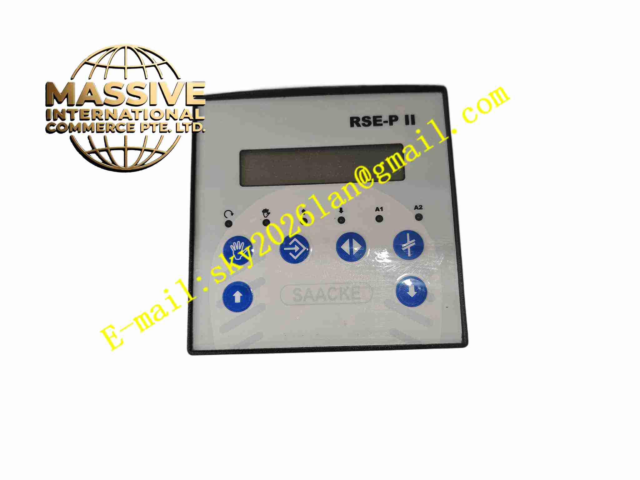
SAACKE RSE-PII
Technical Specifications Brand: SAACKE Model: RSE-PII Power Supply: 90 VAC to 264 VAC, 50/60 Hz Power Consumption: 20 VA maximum Analog Input: 2 configurable analog channels supporting PT100, potentiometer, 4-20 mA Digital I/O: Multiple relay and discrete I/O points Display: Integrated LCD display with operation keypad Protection Grade: IP40 when panel mounted Operating Temperature: -30°C to +70°C Dimensions: 175 mm × 110 mm × 125 mm Weight: 1.15 kg Safety Compliance: EN746-2, NFPA86, SIL2/SIL3 safety integrity level
Functional Features Full automatic burner ignition sequence control including pre-purge, ignition, flame monitoring and post-purge. PID air-fuel ratio control to optimize combustion efficiency and reduce emission. Dual processor safety architecture for critical safety logic. Flame signal evaluation from UV or IR flame detectors. Built-in safety interlock for low air pressure, high pressure, flame failure and emergency shutdown. Front keypad and LCD for local parameter setup, real-time value display and alarm message readout. Internal fault event log stores alarm and shutdown records for maintenance analysis.
Application Scenarios Marine auxiliary boiler burner control, industrial process heater, thermal oxidizer, refinery furnace, hot water boiler, chemical plant combustion system.
Performance Parameters Emergency shutdown response time less than 500 ms on flame loss detection. Precise PID regulation stabilizes air fuel ratio under load variation. Dual processor cross-check eliminates single point safety failure. Long term stable flame signal evaluation under furnace vibration and heat radiation. Event log retains fault records after power loss.
Material Composition Front Panel: Flame retardant black plastic with membrane keypad and transparent LCD window. Main Housing: Reinforced ABS plastic enclosure. Main PCB: FR4 multilayer PCB with conformal coating for moisture protection. Core Components: Dual industrial microprocessors, signal conditioning circuit, safety sealed relays. Display: Monochrome LCD with LED backlight.
Structural Features Panel embedded cutout mounting design. Front panel integrates LCD, membrane operation keys and status LEDs. Rear terminal block area for power, flame detector, I/O and actuator wiring. Internal circuit board separates safety logic circuit and measurement signal circuit. Sealing gasket between front panel and cabinet cutout.
Working Principle Controller executes pre-programmed burner sequence on start command. It reads pressure, temperature and flame detector signals continuously. Dual processors run safety logic in parallel and cross-check each result. If flame failure or safety interlock violation occurs, safety relay cuts fuel valve immediately and triggers shutdown sequence. PID algorithm adjusts fuel and air actuators to maintain optimal combustion ratio. All operating parameters and fault events save into non-volatile memory.
Installation Requirements Install controller into cabinet panel cutout and tighten rear mounting clips. Use shielded cable for flame detector wiring, separate from ignition high voltage cable. Connect power supply within 90-264 VAC range. Wire fuel valves, air dampers and interlock switches to rear terminals. Configure burner fuel type, sequence timing and safety thresholds after power on. Perform full burner sequence test and flame simulation test before commissioning.
Usage Notes High voltage ignition wiring must not run alongside flame probe cable. Do not modify safety interlock logic without engineering approval. Cut power before opening rear terminal cover. Download event log after shutdown fault. Calibrate flame detector loop periodically during boiler maintenance.