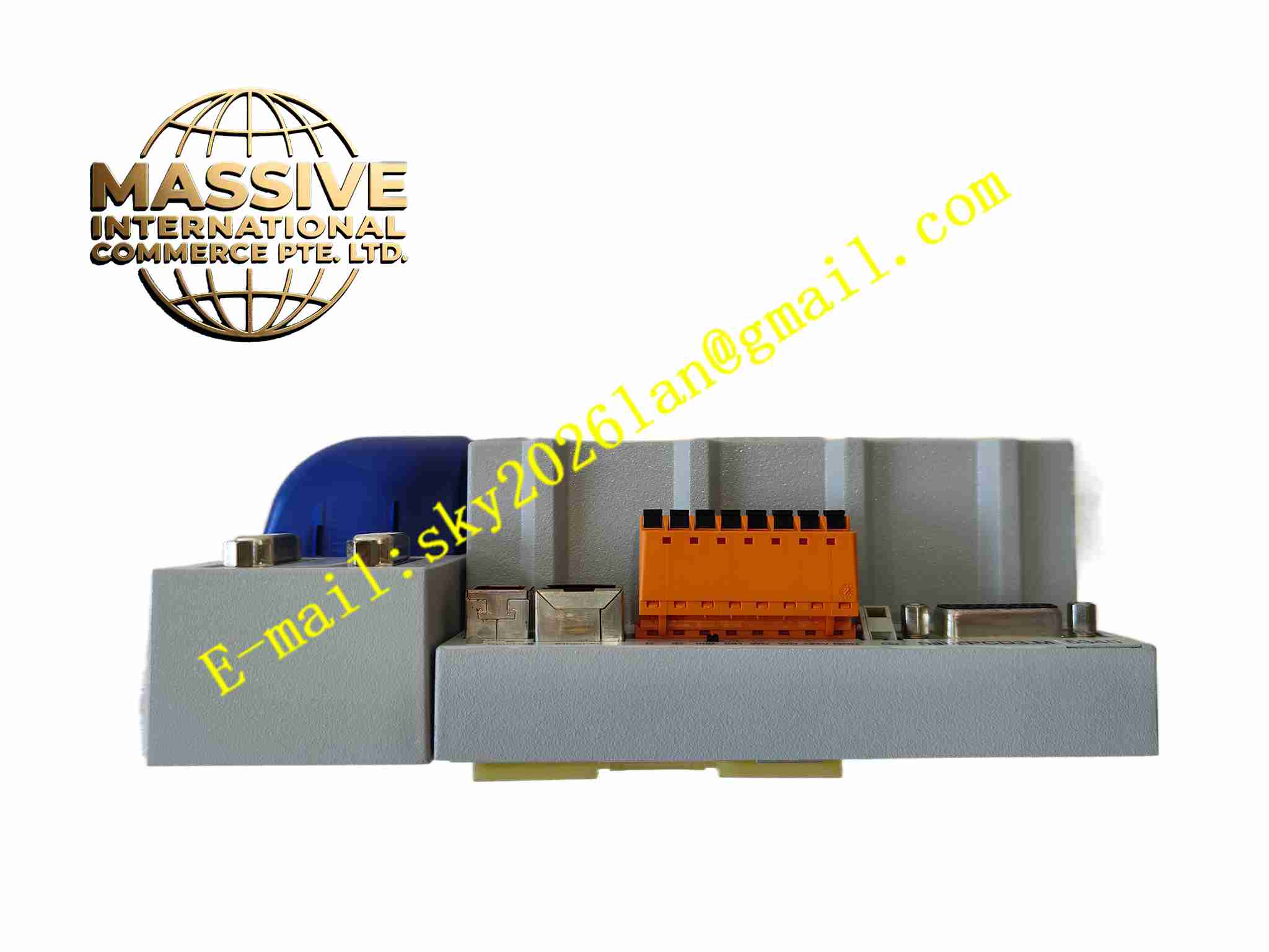
Description
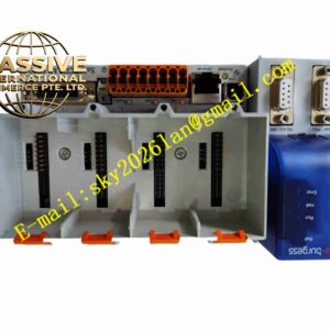
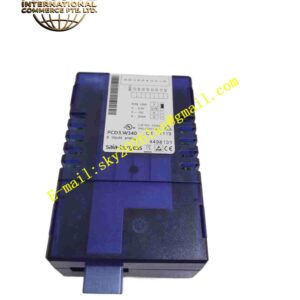
SAIA PCD3.M6340
Technical Specifications: Processor: 32-bit high-performance microcontroller Program memory: 512 KB flash memory Data RAM: 128 KB RAM Power supply: 24 VDC Onboard I/O: 16 digital inputs, 8 relay digital outputs Communication interfaces: 10/100Mbps Ethernet, RS232 programming port, isolated RS485 port Maximum expandable I/O: Up to 512 total I/O points Program execution speed: 0.2 µs per bit operation Operating temperature range: -20℃ ~ +60℃ Storage temperature range: -40℃ ~ +85℃ Relative humidity: 5% to 95%, non-condensing Mounting method: 35mm DIN rail mounting Protection grade: IP20 inside control cabinet
Functional Features: Fully compliant with IEC 61131-3 programming standard, supporting multiple programming languages. Ethernet interface supports Modbus TCP, web server and FTP data transmission. Isolated RS485 port supports Modbus RTU and S-Bus communication protocol. Real-time clock with battery backup for event timestamping and scheduled control logic. Built-in alarm event logging and non-volatile data storage for production and alarm records. Power-on self-test and continuous runtime hardware fault diagnosis. Support hot swap of external PCD3 I/O expansion modules. Web-based HMI function allows remote status viewing and simple parameter modification. PID closed-loop regulation function for temperature, pressure and flow control loops.
Application Scenarios: Building HVAC local control unit, air handling unit controller, small pumping station automation, factory small machine sequence control, lighting group control, refrigeration equipment control, energy monitoring for small commercial facilities.
Performance Parameters: Stable cyclic program execution under medium I/O load. High EMC interference resistance for installation in cabinets with variable frequency drives. Non-volatile flash memory retains user program after complete power loss. 24-hour continuous operation within rated environmental range. Accurate real-time clock for scheduled automatic control tasks.
Material Composition: Main PCB: Multi-layer FR4 glass fiber epoxy printed circuit board. Core components: 32-bit microcontroller, flash memory, RAM, Ethernet PHY chip, RS485 isolation transceiver. Enclosure: Grey flame retardant polycarbonate plastic housing. Terminal blocks: PA66 flame retardant plastic screw terminals with tinned copper contacts. Output relays: Miniature industrial electromagnetic relays.
Structural Features: Compact rectangular DIN rail snap housing. Front panel fitted with LED indicators for power, run status and fault alarm. Front RS232 D-SUB connector for local programming connection. Side terminal blocks for power and onboard I/O field wiring. Right side expansion bus connector to connect PCD3 I/O expansion modules. Internal circuit layout separated into power supply zone, main control logic zone and communication isolation zone. Internal battery compartment for RTC backup battery.
Working Principle: 24VDC power supplies the CPU module. After power-on self-test passes, the microcontroller loads user program stored in flash memory and starts cyclic scanning. Digital input terminals collect on-off status of field sensors and switches. User program executes logic judgment and PID calculation, then drives relay outputs to control valves, contactors and indicators. Ethernet and RS485 communication interfaces exchange data with upper monitoring system and other field controllers. The real-time clock records timestamps for alarms and scheduled tasks. Built-in diagnostic circuit monitors internal hardware state continuously and activates fault indicator when abnormality is detected.
Installation Requirements: Clip the module onto standard 35mm DIN rail inside control cabinet. Wire 24VDC power supply with correct polarity to power terminals. Connect field digital input and output devices to onboard I/O terminals. Connect Ethernet or RS485 bus cables to corresponding communication ports. Connect programming PC via RS232 or Ethernet, download PG5 compiled project. Connect protective earth terminal to cabinet grounding bar. Keep ventilation space around module for heat dissipation. Separate signal cables from high voltage power cables.
Usage Notes: Use anti-static wristband when handling the module. Check power supply polarity before energizing the device. Backup project files before firmware upgrade or program modification. Inspect backup battery periodically and replace when low voltage warning appears. Do not exceed rated relay contact load capacity. Do not operate outside rated temperature and humidity limits. Prevent dust accumulation on terminal connectors.