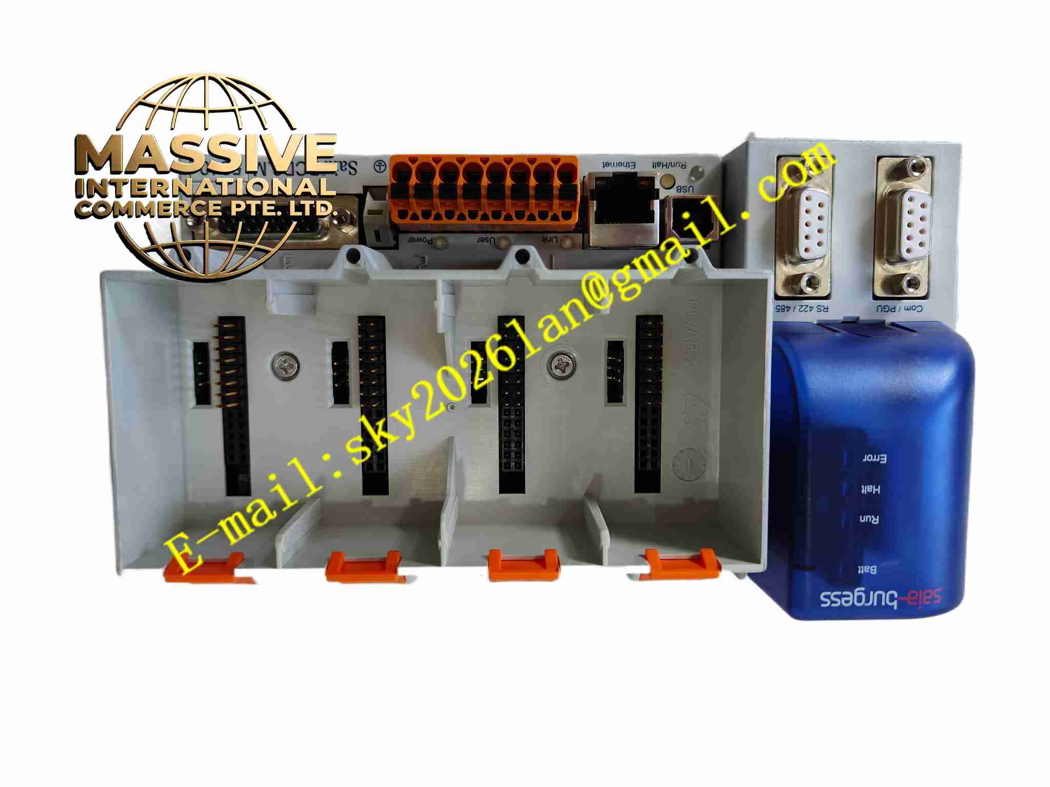
Description
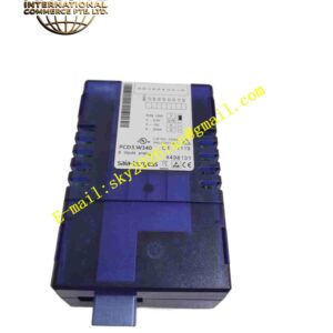
SAIA PCD3.W610
Technical Specifications: Module type: Combined digital input and output expansion module Digital input channels: 16 digital inputs, 24VDC sink/source type Digital output channels: 8 transistor digital outputs, 24VDC Expansion bus: PCD3 system expansion bus Module power supply: Supplied via PCD3 expansion bus Field output power: External 24VDC for output loads Operating temperature range: -20℃ ~ +60℃ Storage temperature range: -40℃ ~ +85℃ Relative humidity: 5% to 95%, non-condensing Mounting method: DIN rail mounting Protection grade: IP20 inside electrical cabinet
Functional Features: 16 digital input channels for collecting binary status of field sensors and switches. 8 24VDC transistor digital output channels for driving low-power field actuators. Each digital input channel equipped with ESD and surge suppression protection. Front panel LED status indicators for every input and output channel. Transmit input status data to PCD3 CPU and receive output commands from CPU via expansion bus. Power-on self-test and continuous hardware fault monitoring. Support stacking installation together with other PCD3 I/O expansion modules.
Application Scenarios: Digital signal expansion for building automation control, valve feedback signal collection, conveyor proximity switch input, solenoid valve control, cabinet status contact monitoring, machine safety switch signal acquisition.
Performance Parameters: Fast response to digital input state change detection. Transistor outputs switch on and off quickly following commands from PLC CPU. 24-hour continuous stable operation under rated load condition. Built-in surge protection absorbs transient voltage spikes from inductive loads. Accurate input status capture even under industrial electrical noise environment.
Material Composition: PCB substrate: Multi-layer FR4 glass fiber epoxy printed circuit board. Core components: Digital logic IC, optocoupler isolation chips, transistor output array, ESD protection diodes. Housing: Grey flame retardant polycarbonate DIN rail housing. Terminal blocks: PA66 flame retardant plastic screw terminals with tinned copper contacts.
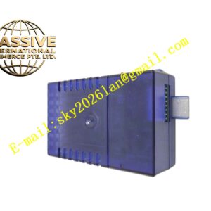
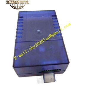
Structural Features: Narrow DIN rail snap housing for stacking with other PCD3 modules. Front panel matrix LED indicators corresponding to each input and output channel. Side terminal block for field sensor and actuator wiring. Left side expansion bus connector to connect previous module. Right side expansion bus port for further I/O expansion modules. Internal circuit divided into field input isolation region, transistor output region and expansion bus interface region.
Working Principle: Module receives logic power supply from CPU over expansion bus. Field 24VDC digital input signals enter optocoupler isolation circuit, converting contact on/off state into digital logic signal for module logic chip. Input status data is transmitted to CPU via expansion bus. When CPU sends output command, logic chip activates corresponding output transistor to switch external 24VDC power to field load. LED indicators reflect real-time on/off status of each channel. Surge protection components absorb voltage spikes generated by inductive loads.
Installation Requirements: Cut off PLC rack power before module installation. Clip module onto DIN rail and connect expansion bus connector. Wire field sensors and 24VDC actuators to module terminal block. Configure I/O address mapping in PG5 PLC programming software. Power on PLC system and download project configuration. Verify input signal reading and output switching function. Connect cabinet protective earth reliably. Separate field I/O wiring from high voltage power cables.
Usage Notes: Use freewheeling diode when driving inductive loads such as solenoid valves. Do not exceed rated current of transistor output channels. Wear anti-static wristband when handling module. Backup PLC project before adding expansion module. Check terminal screw tightness periodically. Do not operate module outside rated temperature and humidity range. Prevent conductive dust entering terminal block.