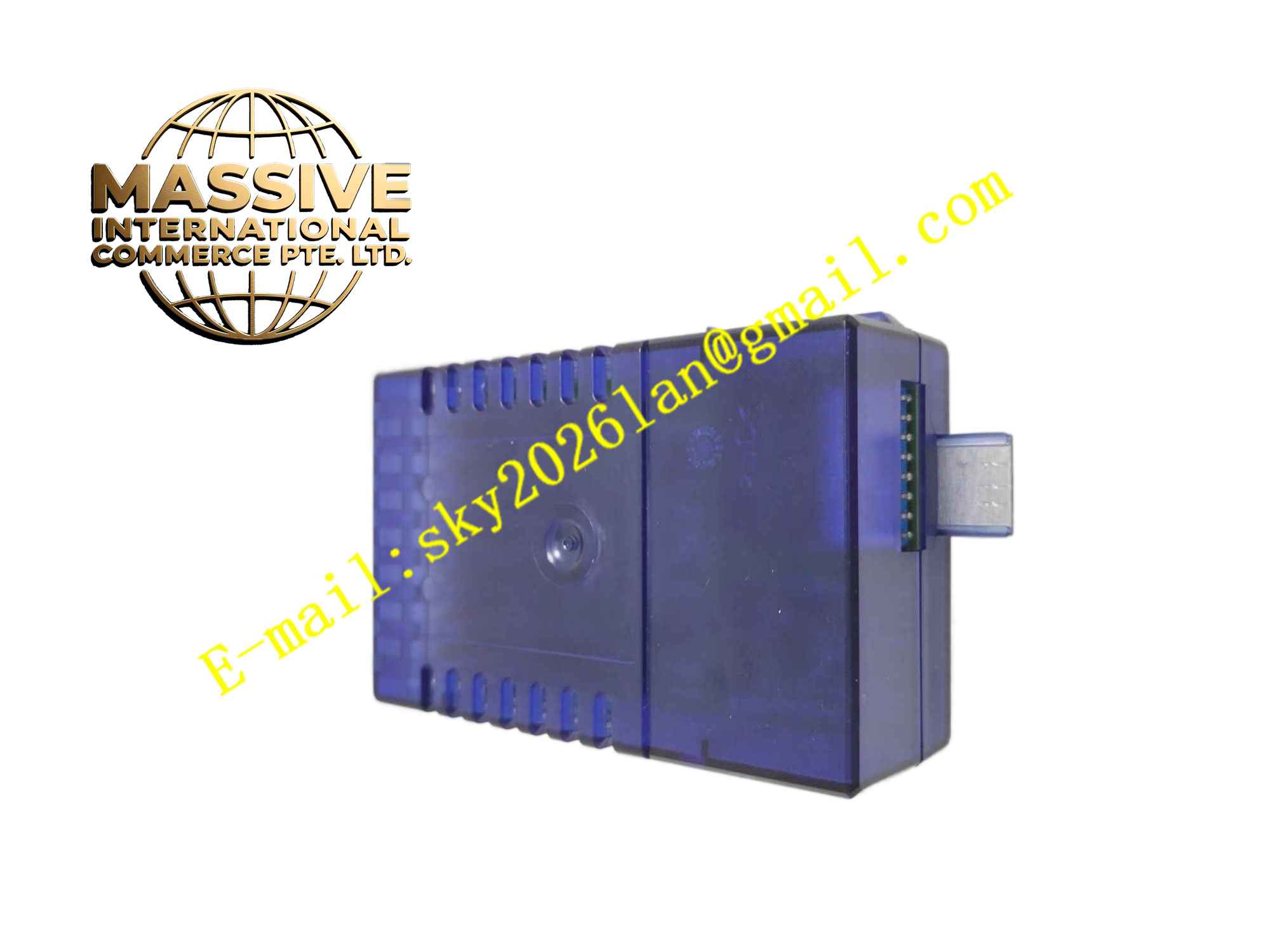
Description
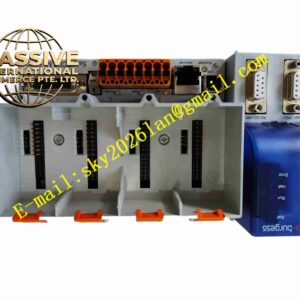
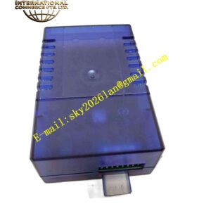
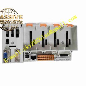
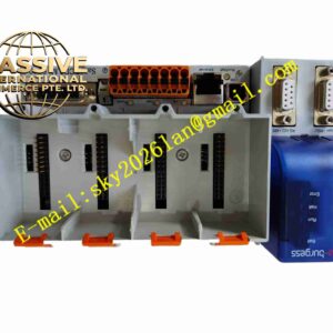
SAIA PCD3.W315
Technical Specifications: Module type: Analog output expansion module Number of channels: 4 analog output channels Signal type: Configurable 0…10 VDC or 4…20 mA per channel Resolution: 12-bit per channel Isolation: Galvanic isolation between module and field loop Power supply: Supplied through PCD3 expansion bus Expansion interface: PCD3 system expansion bus Operating temperature range: -20℃ ~ +60℃ Storage temperature range: -40℃ ~ +85℃ Relative humidity: 5% to 95%, non-condensing Mounting: DIN rail mounting, stacked beside PCD3 CPU Protection grade: IP20 inside control cabinet
Functional Features: 4 independent configurable analog output channels for analog actuator control. Each channel can be set to voltage mode or current mode via PLC configuration software. Galvanic isolation protects PLC system from field loop overvoltage and surge. Output value diagnostic function detects open circuit on current loop wiring. Front panel LED indicators for module power status and channel fault alarm. Receive digital setpoint data from PCD3 CPU over expansion bus. Fast conversion from digital value to stable analog output signal. Power-on self-test and continuous hardware monitoring of output circuits.
Application Scenarios: HVAC proportional valve control, variable frequency drive speed setpoint output, analog indicator display, damper actuator continuous positioning, pumping system pressure regulation, refrigeration valve control.
Performance Parameters: High linearity of analog output signal across full range. Stable output signal with low drift under temperature variation. Fast response to digital setpoint changes sent by PLC CPU. Continuous stable operation within rated load impedance range. Open circuit detection function for 4-20mA current loops.
Material Composition: PCB substrate: Multi-layer FR4 glass fiber epoxy printed circuit board. Core components: Digital to analog conversion chips, signal conditioning amplifiers, optocoupler isolation array, power management IC. Housing: Grey flame retardant polycarbonate plastic DIN rail housing. Terminal blocks: PA66 flame retardant plastic screw terminals with tinned copper contacts.
Structural Features: Standard narrow DIN rail housing for stacking installation with PCD3 CPU and other expansion modules. Front panel LED indicators for power and fault status. Side terminal block for field analog actuator wiring. Left side expansion bus connector to connect to previous module. Right side expansion bus port for connecting additional expansion modules. Internal circuit separated into bus interface area, DA conversion area and isolated field output area.
Working Principle: Module receives power supply and digital command data from CPU through expansion bus. Digital setpoint values from PLC are sent to DA conversion chips. The DA chip converts digital numeric value into analog voltage or current signal. Signal conditioning circuit stabilizes the analog output and drives field actuators. Isolation optocoupler separates low voltage PLC internal circuit from field analog wiring. Diagnostic circuit continuously monitors current loop status and triggers fault LED when open circuit is detected.
Installation Requirements: Cut off PLC system 24VDC power before mounting module. Clip .W315 onto DIN rail and connect expansion bus connector to adjacent module. Wire field analog actuators to module terminal block according to selected signal type. Configure each channel signal type in SAIA PG5 engineering software. Power on PLC system and download project configuration. Verify analog output range and wiring polarity. Ground control cabinet reliably. Use shielded twisted pair cable for analog output field wiring.
Usage Notes: Do not exceed maximum load impedance for 4…20mA current output mode. Check wiring polarity for analog output terminals before power on. Wear anti-static wristband when handling module. Backup PLC configuration before adding new expansion module. Regularly inspect terminal screw tightness. Do not operate module outside rated temperature and humidity range. Prevent dust accumulation on terminal block.