Description
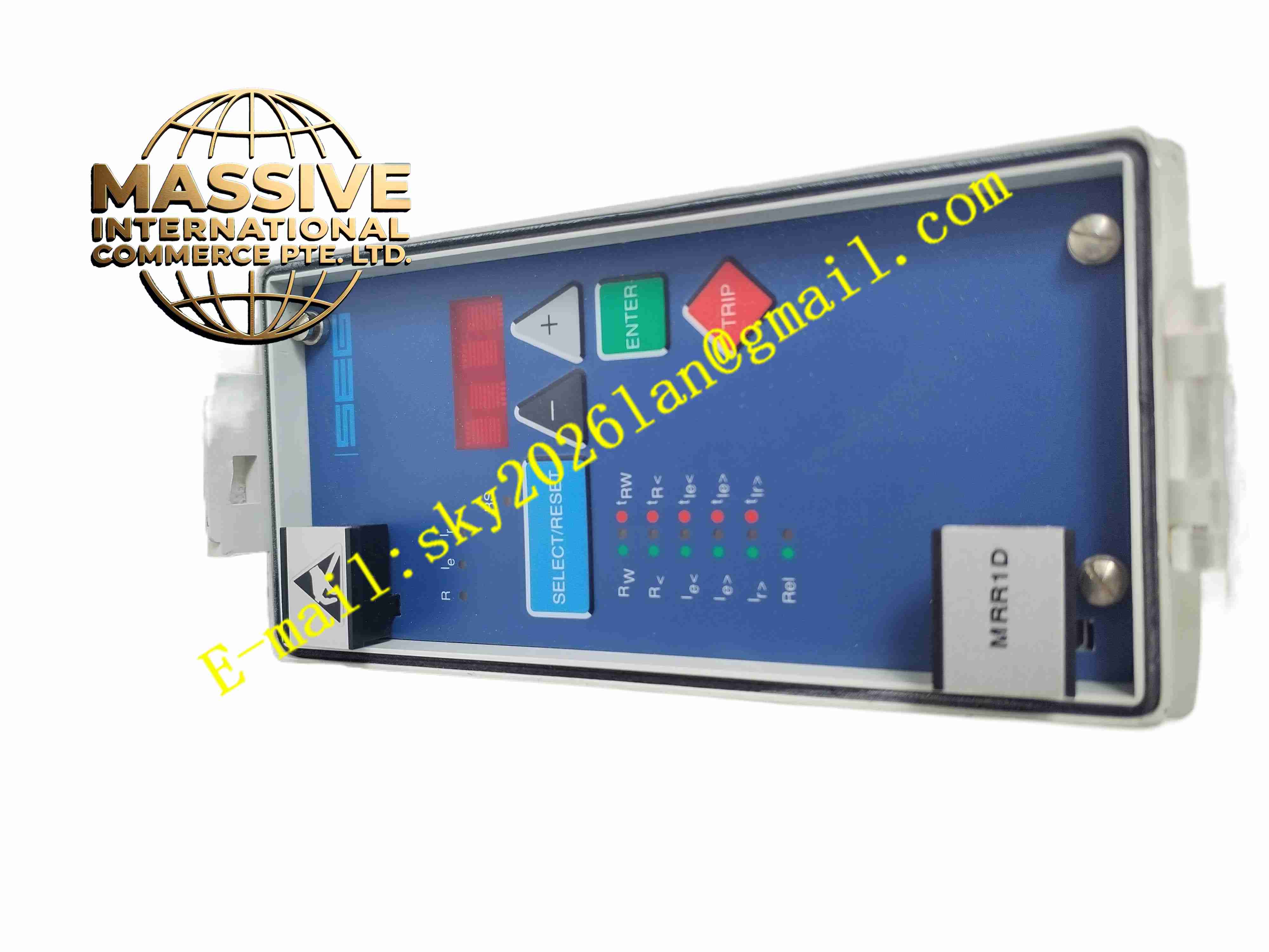
SEG MRR1D
Technical Specifications Insulation resistance measuring range 1 kΩ to 1 MΩ; excitation DC current measuring range up to 25 A DC; auxiliary measuring voltage ±24 V DC; five groups of programmable isolated relay output contacts; RS485 Modbus RTU communication interface; front panel digital display and operation keypad; panel mounting / 19-inch rack mounting; operating temperature range -20℃ to +70℃.
Functional Features Real-time rotor earth fault insulation resistance monitoring with two-stage warning and trip logic; excitation overcurrent and undercurrent dual protection; rectifier bridge diode fault detection via ripple voltage sampling; built-in fault memory to record fault type, action time and pre-fault operation parameters; front panel local parameter setting and value reading; remote parameter configuration and data upload via RS485; hardware anti-interference filtering for high EMC environment.
Application Scenarios Hydroelectric generator rotor protection; thermal power plant synchronous generator excitation monitoring; industrial on-site large backup generator protection; combined cycle power unit rotor safety monitoring.
Performance Parameters Operating ambient temperature -20℃ to +70℃; storage temperature -40℃ to +85℃; relative humidity 5% to 95%, no condensation; measurement tolerance ±2.5% within full operating temperature range; relay operating time less than 100ms.
Material Composition Metal enclosure; multi-layer high precision measurement PCB; analog sampling circuit; embedded microprocessor chip; surge suppression components; electromechanical alarm and trip relays; nickel-plated screw terminals; LED indicators and digital LCD display.
Structural Characteristics Panel mounted rectangular enclosure; front panel equipped with digital display, operation keys and LED status indicators; rear terminal block for rotor insulation measurement wiring, excitation current wiring and relay trip/alarm wiring; internal circuit separates high voltage measuring circuit and low voltage digital processing circuit.
Working Principle Auxiliary measuring voltage injects into generator rotor winding. The relay circuit calculates rotor insulation resistance by measuring leakage current. Current sampling circuit collects excitation DC current and ripple voltage of rectifier bridge. Embedded processor compares measured values with preset protection thresholds. When measurement exceeds warning threshold, warning relay activates. When value reaches trip threshold, trip relay cuts off generator excitation circuit. Fault data saves permanently in non-volatile memory.
Installation Requirements Mount relay on control cabinet panel or standard 19-inch rack. Wire rotor insulation measurement circuit and excitation current sampling circuit strictly according to wiring schematic. Connect trip relay contact to excitation breaker control circuit. Configure protection threshold parameters via front keypad or HTL/PL-Soft4 software. Complete cabinet protective earthing and perform loop test after commissioning.
Usage Notes Check wiring polarity and insulation resistance of measuring cable before commissioning. Backup protection setting parameters before firmware upgrade. Inspect relay contact wear periodically. Keep relay cabinet dry and free of conductive dust contamination.