Description
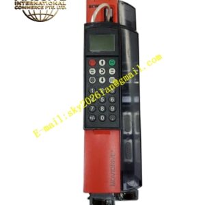
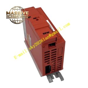
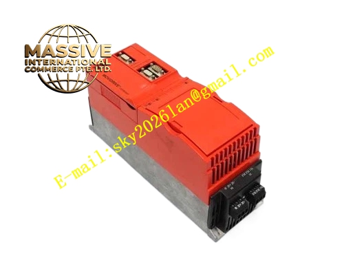
SEW MCS41A0015-5A3-4-00
Technical Specifications:
- Brand: SEW-EURODRIVE
- Series: MOVIDRIVE compact MCS41A
- Recommended Motor Power: 1.5 kW
- Input Voltage: 3-phase AC 380–500V, 50/60 Hz
- Control Modes: SERVO (primary), VFC, CFC
- Encoder Feedback: Supported (closed-loop capable)
- Operating Quadrants: 4Q (with brake chopper)
- Line Filter: Radio interference suppression Class A installed
- Protection Rating: IP20
- Operating Temperature: 0°C to +50°C
- Certifications: CE, UL
- EMC Standard: EN 61800-3 (Class A)
Functional Features:
- SERVO Control Mode: High-dynamic servo-grade control with position, speed, and torque control loops for precision motion applications
- CFC Closed-Loop Control: Current flux control with encoder feedback for precise torque regulation
- IPOS+ Integrated Positioning System: Autonomous motion sequence control within the inverter, reducing PLC dependency
- PROFIBUS-DP Communication: Integrated fieldbus interface for seamless integration into industrial automation networks
- Comprehensive Protection Suite: Overcurrent, overvoltage, undervoltage, overheating, phase loss, and ground fault detection
- Modular Design: Compact Size 1 form factor with removable connection unit for efficient maintenance
- System Bus (SBus): Standard networking interface for multi-drive coordination via MOVILINK protocol
- Incremental Encoder Support: Dedicated X14 and X15 encoder interfaces for motor feedback and simulation output
Application Scenarios:
- Precision positioning systems in automation machinery
- Small servo-driven conveyor and transfer systems
- Packaging machinery requiring precise registration
- Labeling and marking equipment
- Small machine tool axis drives
- Robotic handling and pick-and-place systems
Performance Parameters:
- Torque Capability: At least 150% torque at standstill (with encoder)
- Output Frequency Range: 0–550 Hz
- Speed Control Accuracy: ±0.2% (closed-loop SERVO mode)
- Overload Capacity: 150% rated current for 60 seconds
- Dynamic Response: High-bandwidth current control loop optimized for servo-grade applications
Material Composition:
- Industrial-grade IGBT power modules
- Coated circuit boards for dust and moisture protection
- Aluminum heat sink for thermal dissipation
- Integrated EMC filter components
- Steel enclosure with powder-coated finish
Structural Features:
- Compact Size 1 cabinet-mount form factor
- Removable connection unit with separable power and motor terminals
- X1: Power supply connection (1/L1, 2/L2, 3/L3), separable
- X2: Motor connection (4/U, 5/V, 6/W)
- X3: Braking resistor connection (8/+R, 9/–R) and PE connection, separable
- X4: Connection for DC link connection –U
- X10: Electronics terminal strip for control signals
- X14: Incremental encoder simulation output or external encoder input (9-pole Sub-D socket)
- X15: Motor encoder input (9-pole Sub-D socket)
- X30: PROFIBUS-DP connection (9-pole Sub-D socket)
- TERMINAL slot for DBG keypad or USS21A/USB11A option
- LED status and diagnostic LEDs
- Shield clamp for power section grounding
Working Principle:
The inverter converts AC input to DC through a three-phase rectifier, stores energy in DC bus capacitors, and synthesizes a variable-frequency PWM output through IGBT switching. In SERVO mode, the drive operates with cascaded position, speed, and torque control loops. The innermost current control loop regulates electromagnetic torque with high bandwidth, while the speed and position loops provide precise trajectory following. Encoder feedback from the motor encoder connected to X15 enables closed-loop operation.
Installation Requirements:
- Mount vertically in a control cabinet with adequate ventilation
- Maintain minimum clearance above and below the unit for airflow
- Use shielded power and motor cables with proper 360° shield grounding
- Ensure motor cable phase sequence matches U-V-W terminal markings
- Connect braking resistor to dedicated brake terminals when dynamic braking is required
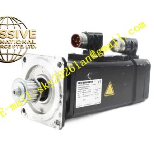
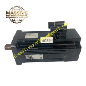
- Connect motor encoder cable to X15 terminal for closed-loop operation
- Ambient temperature must remain within 0°C to +50°C range
- Humidity must be maintained between 30% and 60% RH
Usage Notes:
- Perform motor initialization and encoder calibration when connecting a new motor
- Use MOVITOOLS MotionStudio software for parameter configuration and commissioning
- Verify power supply voltage stability within ±10% tolerance before operation
- Never connect or disconnect motor cables while the inverter is energized
- Monitor fault codes via the integrated LED display or MOVITOOLS software
- Clean heat sink dust regularly; accumulation exceeding 2 mm thickness requires cleaning
- Verify grounding resistance is less than 1 Ω
- The MOVIDRIVE compact drive inverters do not perform safety functions without higher-level safety systems; use external safety systems to ensure protection of personnel and equipment